Here's what I did while I'm waiting. I put 2 more 1/4W 1R safety fuses in, so I could take measurements, as long as the relay doesn’t trip (as in, never plugged in the PSU to the amp board)
Compared all measurements to my working AMP200 (resistance and voltage) on every wire from the PSU to the Amp board. They were all within +/-10%... except for the -15V rail, its -19.4, compared to my AMP200 which is -15.47.
Any idea why that might be off? I have re-checked all the resistors and they measure within spec, all the Caps are new Nichicon and TDK ceramic (didn’t replace the C09/C10 0.1uF/100v, they were still good and looked difficult to remove/replace).
Is the regulator a -15VDC regulator, I have to ask. Is pin 1 grounded? Not much else it could except a bad regulator.
Craig
Craig
I feel like a total "idiot", but you are correct Sir. I tested for DC on the IN and it's 28vdc, right what it should be and the OUT shows -19.46vdc, what it shouldn't be.
How could I check my other 7915 before I install? Or is that not possible? Sure glad I bought 2.
Thanks again for the assist.
How could I check my other 7915 before I install? Or is that not possible? Sure glad I bought 2.
Thanks again for the assist.
Not unless you have a separate power supply or can use jumpers to connect it to the amp's PS. Did you use the Arctic Silver and short it out?
Craig
Craig
I used Arctic Silver on the 7815 and 7915 and the 7815 is fine.
I just installed the other 7915 and it is -19.4V as well. I didn't install the heatsink yet either, so it can't be the Arctic Silver. Do they typically have issues?
I just installed the other 7915 and it is -19.4V as well. I didn't install the heatsink yet either, so it can't be the Arctic Silver. Do they typically have issues?
well they both have the same 28V IN, but 7815 is +15v and the 7915 is -19.3v (both of them I installed).
Digikey was very nice and they are sending me replacements today. I guess we will get back to this in a couple days.
edit - I found a 7915CV from a pre-amp I just got in the mail today from China. Stole it, installed it... and I have +14.95V, -15.05V.
Do you think I am safe to power up, even thought I have the 1/4-watt resistor still in??? My AMP200 has at least a 1/2-watt. I did watch the voltage on turn-on and it only goes up to 0.189 V through the resistor, but no idea how many amps.
Thoughts????
Last edited:
We already know the regs run hot due to somewhat high input voltage AND heavy(?) load so the resistors will probably go again. I don't know how hard it is to get the PCB out so I'd just wait for the larger resistors.
Craig
Craig
IT"S ALIVE!!!!! I replaced the 1/4 watt 1-ohm safety resistors with 2-watt, which are still smaller than the ones in my Amp200 (must be 3 watt???) Oh well, that was the biggest I bought and they have survived on-off about 6 times already, as well as 2 hours of idle with no load. Listening to music for 30 minutes now and it sounds good.
I did put heat-sinks on the IC's, but they are running at 80F after 2 hours, so I think they are running cooler than I thought they would. One has Arctic Silver and one doesn't, and they are within 0.2 degrees, so I don't think the AS makes any difference.
Thanks again @llwhtt for all the assistance. Glad to have my amp back!
Now measure the AC voltage across one of the resistors so we can get an idea of the current thru them. Since the resistors are 1 Ohm the voltage and current will the same numbers. If you .5 VAC the current will be about .5 Amps, and that would be .25 Watts.
Craig
Craig
In standby - they both measure 0.08Vac
On and playing music - they both measure 0.188Vac
IR thermometer shows 122F on one near edge of board and 134F on the middle one. But not hot to the touch, I can put my finger on them without a problem?
Oh and I remeasured the IC's and the fins on the heat sink measure 100-110F after some music has been playing at pretty high volume for 30+ minutes. No heat sinks they were getting to 120-125, so I guess they are worth $0.70.
Well I have had a failure with a different AMP300 - but thanks to the help here, a very quick test and it was the 1-ohm safety resistors (R01 & R02). Replaced with 1-watt I had on hand and the amp has been working well.
Question
I added heatsinks to the low-level voltage regulators (7815 and 7915) on the PSU board. They are converting 28vDC to +/-15vDC
However, the 7815 is running very hot even with the heatsink, hot enough that I can only put my finger on it for 4-5 seconds or risk a burn. shows 140-150F, but seems hotter than that? The 7915 seems happy at about 120F.
Is this an indication the 7815 is failing due to a resistance change or impeding failure?
Attachments
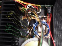
Hi,
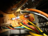
I have AMP300 with the same symtom. Is it safe to assume that I need to replace R01 and R01 as pictured with green arrow? Where can I get the safety resistor?
Thanks.
I have AMP300 with the same symtom. Is it safe to assume that I need to replace R01 and R01 as pictured with green arrow? Where can I get the safety resistor?
Thanks.
Hi Experts,
Thanks bullittstang for guiding me getting numbers below. Please see attached or below for the measurements I am getting. Highly appreciate any help you can provide to get this amplifier back up and running.
It's been broken and disconnected for a while. When I turned it on two days ago, the first time it worked for 1 or 2 seconds and I heard a click coming from the amplifier and stopped working. It turns on, but not doing anything at all the second time I tried.
Resistors
R01 - 1.9
R02 - 1.9
R05 - 10.8
CNA02 readings:-
(+24V(green) = +26.4
POWER (white - which should be +12V) = +11.9v
+15V(red) = +14.9v
-15V(yellow) = -14.9v
CNA101,CNA201:-
DV Voltage = -3.6 and +2.2
AC Voltages = 21.1v, 21.1v and 46.7v, 46.7v
Attachments

Two things:
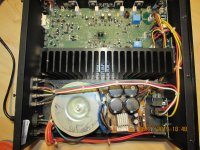
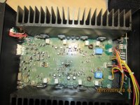
1). Up load pictures of your board, especially the amp board (where the RED, BLACK,YELLOW plug into) where the transistors are on the heatsink and board.
2). Put your probes on the speaker outputs, red to red and black to black. Nothing else plugged in (I.e input or speakers) . Your checking for DC on the outputs, this will trigger the protection circuit after 0.5-1.0Vdc on the speakers. Might have to do it a couple of times, because the DC will only be there for a few seconds before the relay clicks out the signal.
Sounds like you have ruled out the transformer and the low voltages (+24, +12, +15, -15). The next thing is either protection or a blown output/driver transistor.
Last edited:
Might sound elementary BUT are you sure you have the switch on the back to ON, not Auto or Trigger? Just ruling that out.
Next unplug both red/black/yellow connectors and let’s make sure you have ~60Vdc getting to that point.
If you do, then the Power supply is working and focus on amp board. If not, then we should start with the power supply and eliminate all the resistors and rectifier as the issue.
Next unplug both red/black/yellow connectors and let’s make sure you have ~60Vdc getting to that point.
If you do, then the Power supply is working and focus on amp board. If not, then we should start with the power supply and eliminate all the resistors and rectifier as the issue.
The switch on the back is set to Normal on.
Both red/black/yellow connectors I don't have ~60Vdc getting to that point. I am getting +5.6 and -3.7 on one and on the other +6.5 and -5.8.
Both red/black/yellow connectors I don't have ~60Vdc getting to that point. I am getting +5.6 and -3.7 on one and on the other +6.5 and -5.8.
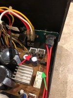
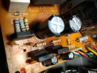
Looking at your PSU pic that you numbered.
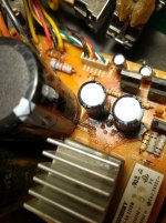
It looks like one of the 1000uF/50v capacitors has a split right down the negative marking????
Also looks like something has discolored the board there too. Either heat or the dielectric from the cap.
I would clean up the boards too - makes it much easier to spot a burn or crack when you aren’t fighting with dust and dirt.
Looking at your PSU pic that you numbered.
It looks like one of the 1000uF/50v capacitors has a split right down the negative marking????
Also looks like something has discolored the board there too. Either heat or the dielectric from the cap.
I would clean up the boards too - makes it much easier to spot a burn or crack when you aren’t fighting with dust and dirt.
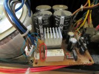
Good eyes!! You are correct. one of the 1000uF/50v capacitors has a split. Looks like liquid was oozing out of it. The original black color capacitor is also discolored. The discolored on the board was caused by the the capacitor liquid I guess. Is this replaceable? Do I need to replace both?
I touched the capacitor that's discolored, it moved slightly back and forth. The other one doesn't do that...
Last edited:
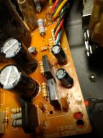
Please see images of the problem area attached. I have clean up the dust.
Also, the first picture, I circled the area in red that looked rusted or discolored that's not related to 1000uF/50v capacitor leak...
Also, the first picture, I circled the area in red that looked rusted or discolored that's not related to 1000uF/50v capacitor leak...
Attachments
Last edited:
- Status
- Not open for further replies.
- Home
- Amplifiers
- Solid State
- AudioSource AMP300 Troubleshooting