Ashok,
I don't have the faintest clue. I used a CAD design program called Front Panel Express. I then sent it to Front Panel Express in Washington, who did the engraving.
Best,
Anand.😀
I don't have the faintest clue. I used a CAD design program called Front Panel Express. I then sent it to Front Panel Express in Washington, who did the engraving.
Best,
Anand.😀
Hallo Anand,
What do you feel was the contribution the input transformers made to the sound?
Regard,
Bas
What do you feel was the contribution the input transformers made to the sound?
Regard,
Bas
Plitron
Hii Peter
For Plitron 300va toroid
- how much voltage ?
- with secondary winding (2X --V) ?
thanks for info
Peter Daniel said:
The chassis pictured here: http://audiosector.com/chassis_integrated.shtml is available as a kit at $250. All accessories are extra:
Brass cones $15/set
Knobs $18 ea.
Wooden sides $10 unfinished, $20 finished maple, $40 exotic wood
Shaft extenders $10/set
RCAs $3.50 ea
Cardas patented binding posts $35/set
Noble pot $22
Source selector $8 (different than pictured)
AC module $3
Plitron 300VA toroid $85
Hii Peter
For Plitron 300va toroid
- how much voltage ?
- with secondary winding (2X --V) ?
thanks for info
Jeffrey,
I believe it is a 300VA Plitron with 2X22V secondaries. Either 115V or 230V can be wired for the primary. I believe its this one here .
The big difference is that Peter probably has them in stock and can ship right away 😀 . Plitron usually takes 3-4 weeks including manufacturing and shipping time .
.
Best,
Anand.
I believe it is a 300VA Plitron with 2X22V secondaries. Either 115V or 230V can be wired for the primary. I believe its this one here .
The big difference is that Peter probably has them in stock and can ship right away 😀 . Plitron usually takes 3-4 weeks including manufacturing and shipping time
.Best,
Anand.
Hi Anand,
I think the lettering looks engraved - machined.
Etching might not be so deep (?).
Looks nice in any case.
Cheers,
Ashok.
I think the lettering looks engraved - machined.
Etching might not be so deep (?).
Looks nice in any case.
Cheers,
Ashok.
Peter:
on your audiosector PSU boards, do the lines on the front side of where the diodes go mark the locations for the common-cathode diodes? If I use these, do I still need to populate all four locations (I would assume only 3 of the four are necessary)? Also, if you use the Jensen 4-pole caps, then you need to cut the 5 traces on the back and then just use the output pads on the far right of the boards? Finally, is there any reason that I cannot "share" the input pads between the bridge and the first capacitor for the R9/R10 that NP uses on the F4? This is a 2.2k resistor that goes from the rail to ground before the first capacitor ... I would then bring the excess leads up from the back to connect to the rectifier portion of the board...
Thanks!
are DIN connectors suitable?
hi, wanted to ask are the DIN connectors (not mini-DIN) suitable for power connector between gainclone power supply out and amp power in? i have one 225VA 2x21V toroidal transformer and one diode bridge feeding the stereo conf amp (like patek or sth). can i use DIN connectors for this ? they are rated 4A i guess...
hi, wanted to ask are the DIN connectors (not mini-DIN) suitable for power connector between gainclone power supply out and amp power in? i have one 225VA 2x21V toroidal transformer and one diode bridge feeding the stereo conf amp (like patek or sth). can i use DIN connectors for this ? they are rated 4A i guess...
You could probably use them, but 3 or 4 pin Neutrik would be more suitable (rated 16 and 10A respectively).
luvdunhill said:on your audiosector PSU boards, do the lines on the front side of where the diodes go mark the locations for the common-cathode diodes? If I use these, do I still need to populate all four locations (I would assume only 3 of the four are necessary)? Also, if you use the Jensen 4-pole caps, then you need to cut the 5 traces on the back and then just use the output pads on the far right of the boards? Finally, is there any reason that I cannot "share" the input pads between the bridge and the first capacitor for the R9/R10 that NP uses on the F4? This is a 2.2k resistor that goes from the rail to ground before the first capacitor ... I would then bring the excess leads up from the back to connect to the rectifier portion of the board...
Those boards have been described here: http://www.diyaudio.com/forums/showthread.php?postid=1237660#post1237660 The dual lines mark the metal tabs of TO-247 diodes. While you only need 3 of dual cathode diodes to build a bridge, the board requires 4 of them (unless you modify connections). The reason for that is compatibility with other diode types one may choose to use here.
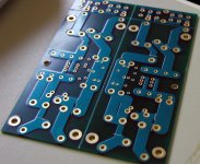
If you use Jensen caps, to implement 4 pole feature properly, you need to cut traces underneath in 5 spots, marked by white lines (see attached pic). That will separate input and output pads for 4 pole configuration. In that case output is taken from far right pads (V+ and GND).
If you want to use 2.2k resistor, it's best to install it accross the pins of first cap, (separate resistor per each bridge).
Attachments
I never thought an assembly manual for such a simple circuit was needed.
You can find schematics for amp and power supply sections here: http://www.audiosector.com/lm4780.shtml
If you click on Application Notes link, it will get you to pics and short info I posted on a Forum.
You can find schematics for amp and power supply sections here: http://www.audiosector.com/lm4780.shtml
If you click on Application Notes link, it will get you to pics and short info I posted on a Forum.
Member
Joined 2002
Peter Daniel said:I never thought an assembly manual for such a simple circuit was needed.
You can find schematics for amp and power supply sections here: http://www.audiosector.com/lm4780.shtml
If you click on Application Notes link, it will get you to pics and short info I posted on a Forum.
Simple for you Peter, not simple for others, however he may just be wanting instructions so he can build it 100% perfect so he has no troubles.
Just a thought.
Jase
I don't see how to make better instructions than what already has been posted: http://www.diyaudio.com/forums/showthread.php?postid=636565#post636565
thats a great pic, but it is difficult to find without digging through 75 pages of info!!!
do you have a Power supply pic like that???
do you have a Power supply pic like that???
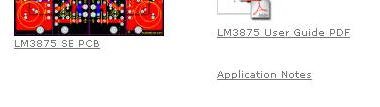
When I released both amp boards, I posted detailed instructions here on a forum, in this thread. To make it easier find it later, I made links from the pages describing each kit; just click on 'Application Notes" shortcut.
The PS for LM4780 kit is basically the same as for LM3875, and you can see it here (LM3875 PS): http://www.diyaudio.com/forums/showthread.php?postid=584429#post584429
Please note that in LM4780 PS diodes are reversed though, and black stripes always indicate metal tabs.
The PS for LM4780 kit is basically the same as for LM3875, and you can see it here (LM3875 PS): http://www.diyaudio.com/forums/showthread.php?postid=584429#post584429
Please note that in LM4780 PS diodes are reversed though, and black stripes always indicate metal tabs.
Attachments
Member
Joined 2002
- Status
- Not open for further replies.
- Home
- More Vendors...
- Audio Sector
- AudioSector-chip amp kits, dacs, chassis