I am not able to make much of this 🙁
What is the output impedance of this thing measured at the output?
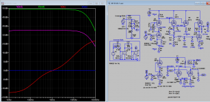
The green curve is output impedance of as-built schematic, don't bother the others if you don't do sim. Output impedance is frequency dependent, you read off the left hand scale, 5.5k @10hz,..... to 10.5k @100khz on the right. Because the result impedance is the combined transformer and tube impedance, if there is insufficient inductance, the impedance will be lower which leave only the tubes output impedance. The dip also means a loss of gain, eg due to uncompensated cathode resistor.
Last edited:
The green curve is output impedance of as-built schematic, don't bother the others if you don't do sim. Output impedance is frequency dependent, you read off the left hand scale, 5.5k @10hz,..... to 10.5k @100khz on the right.
Are you serious?
With a 33:1 output transformer the anode impedance of the 5687 will be transformed down by a factor 1089.
Output impedance should be under 10 ohm.....
On the secondary yes, the sim referred to primary, I can give you sec impedance if you want.Are you serious?
With a 33:1 output transformer the anode impedance of the 5687 will be transformed down by a factor 1089.
Output impedance should be under 10 ohm.....
Last edited:
The "overall output impedance" as you name it should be the output impedance measured at the output of this preamp, not the anode impedance.
But when your sim is somehow reliable the real output impedance is indeed under 10 ohm.
Not difficult to estimate without a sim though.
Thanks.
But when your sim is somehow reliable the real output impedance is indeed under 10 ohm.
Not difficult to estimate without a sim though.
Thanks.
The copper resistance is also in series. However this is not really relevant. Low voltage output with a lot of distortion is more relevant. With that primary voltage swing you can almost drive a 300B directly! Waste of time and money in exchange of horrible results: Is there a Nobel Prize for this?

This is the testing results, I have tested 36 group of data, and choose the highest inductance of these datas, and use the following formula to caculae the magnetoconductivity of the coil


The magnet conductivity is about 900.
Is it right?
The magnet conductivity is about 900.
Is it right?

If you give information about core and transformer then one can say something about number of turns for 100H inductance.
What core are you going to use? SG series, SU series or other? What size?
Are you making a core type (i.e. 2 coils on 2C core) or shell type (one coil on 4C core) transformer?
Operative DC current?
Max primary voltage?
What core are you going to use? SG series, SU series or other? What size?
Are you making a core type (i.e. 2 coils on 2C core) or shell type (one coil on 4C core) transformer?
Operative DC current?
Max primary voltage?
If you give information about core and transformer then one can say something about number of turns for 100H inductance.
What core are you going to use? SG series, SU series or other? What size?
Are you making a core type (i.e. 2 coils on 2C core) or shell type (one coil on 4C core) transformer?
Operative DC current?
Max primary voltage?

This is the size of the core
And 30mm in dimension
Since this is a second hand core, I don't know if it is SG or SU.
I want to make one coil on 4C core
The operative D.C. Current is 10ma
Max primary voltage is about 260V in DC
View attachment 629886
This is the size of the core
And 30mm in dimension
Since this is a second hand core, I don't know if it is SG or SU.
I want to make one coil on 4C core
The operative D.C. Current is 10ma
Max primary voltage is about 260V in DC
So it is 13x30 core area (or cross-section if you like) for a total of 26x30 for the 4C core?
Max primary voltage is not the DC voltage but the max signal RMS voltage you want to apply at the lowest frequency. Say 100V rms at 20Hz? max signal means undistorted in theory.....
100V rms means that with 33:1 turn ratio the max secondary voltage will be 3V rms at that frequency.
This is your core:
High Efficient Transformer Kmac-32 (equ. Amcc-32) Amorphous C Core - Buy Amorphous C Core,Amcc Core,Transformer Iron Core Product on Alibaba.com
Check max. T (1.56); it's lower than for HiB silicon steel.
Afe for two complete c-cores is 6.4 cm².
High Efficient Transformer Kmac-32 (equ. Amcc-32) Amorphous C Core - Buy Amorphous C Core,Amcc Core,Transformer Iron Core Product on Alibaba.com
Check max. T (1.56); it's lower than for HiB silicon steel.
Afe for two complete c-cores is 6.4 cm².
Yes, that looks like it....😉
I found UK version of AN M10. The output stage is two 47k connect in parallel, fully bypassed. I sim with new value the freq response is flat down to 10hz. The riaa eq section is a little different too. If you're an owner of M10 appreciate check what version and values they actually are as schematic found is a little blur.
Attachments
Last edited:
Preamp output stage seems plausible: 20 dB of gain (6072 SRPP has gain of 20, and 5687 stage with output transformer included has some 0.5 gain. Total gain = 10 (20 dB)).
So, assuming that core is the right one, with 4511 turns and 0.16 mm TOTAL airgap (i.e. 0.08 mm spacer x2) the transformer should look like this (at low frequency):
1) L=105H
2) max operative DC current 12-13 mA (this means that if higher ande current is used inductance will start to decrease seriously)
3) The max signal at the primary @20Hz for 10mA anode current will be 88 Vrms
This means that the max induction @20Hz with 10mA anode current and 88V rms applied will be:
Bmax = Bdc +Bac = 0.72T
This is far away from saturation but more signal is not possible because Bac cannot be bigger than Bdc. More turns are needed, gap recalculated.....however this also means more losses (both copper and leakage/parasitc).
- Home
- Amplifiers
- Tubes / Valves
- Audio Note M10 Clone