Beware that those above are the transformer's spces. It will be fine but the tube won't be so happy to deliver 88V rms @ 20Hz for about 2.5 Vrms ouptput with 33:1 ratio!
P.S.
I am just seeing that the magnetic path lenght of your core might a bit diffrent. If 0.08 mm spacer will give lower inductance then try 0.05 mm spacer and check that inductance doesn't decrease seriously for 10-20% higher DC current.
I am just seeing that the magnetic path lenght of your core might a bit diffrent. If 0.08 mm spacer will give lower inductance then try 0.05 mm spacer and check that inductance doesn't decrease seriously for 10-20% higher DC current.
@ jerrylong:
Some remarks if you want to copy the complete design:
- phono stage gain is 36 dB (x 63);
- with 5 mV phono input, output signal of phono stage is 315 mV;
- you need at least 20 dB (10x) of gain in the output stage to drive power amplifiers;
- the 6072 SRPP/5687 will provide you with the necessary gain, but there are problems with input signal to the 5687 grids, the high anode AC voltage of the 5687, and last but not least the output transformer;
- better skip the 6072 SRPP in the output stage;
- there are several options for a better output stage: for example single tube like E810F, 6C45, D3a with 5:1 step down output transformer. Or, if you prefer to use 5687, use one halve for voltage gain and direct couple it to the other halve being a cathode follower (can be done with output transformer, but a simple capacitor output might work equally well).
P.S.
I am just seeing that the magnetic path lenght of your core might a bit diffrent. If 0.08 mm spacer will give lower inductance then try 0.05 mm spacer and check that inductance doesn't decrease seriously for 10-20% higher DC current.
I found a winding scheme in my archive, using the same cores (2 x AMCC-32).
That transformer had 4800 primary turns.
With 0.12 mm gap (2 x 0.06 mm) I measured 90 H of primary induction.
Measurement was done with a professional inductance meter (low voltage at 100 Hz, and no DC was applied).
I found a winding scheme in my archive, using the same cores (2 x AMCC-32).
That transformer had 4800 primary turns.
With 0.12 mm gap (2 x 0.06 mm) I measured 90 H of primary induction.
Measurement was done with a professional inductance meter (low voltage at 100 Hz, and no DC was applied).
Yes Pieter, with no real data one can get close and then adjust in small steps. For real data I mean effective permeabilty VS Hdc (or inductance/(turns)^2 VS turns x Ampere for the specific core) for different g values (for different air gaps).
g is related to total air gap by the relation Lm * g=total gap.
If the gap is right, inductance will be almost constant up to a certain dc current (with extremely gentle slope down) and then get to a knee and start to drop very fast.....
Kondo ≠ Audio Note UK
I haven't gone through all the posts in this thread so I don't know if anyone mentioned that the schematic in post#3 is from Audio Note JAPAN, aka, Kondo, before the divorce from Audio Note UK. Audio Note Japan cannot use the name Audio Note legally outside of Japan. Before the forming of the UK company, many circuits of ANJ were circulated in diy community, including the legendary Ongaku 211 amp. Some of these circuits were published in Sound Practices in the 90s. The posted M10 schematic is from Kondo Japan and has nothing to do with the circuit by Andy Grove of ANUK that bears the same name.
I haven't gone through all the posts in this thread so I don't know if anyone mentioned that the schematic in post#3 is from Audio Note JAPAN, aka, Kondo, before the divorce from Audio Note UK. Audio Note Japan cannot use the name Audio Note legally outside of Japan. Before the forming of the UK company, many circuits of ANJ were circulated in diy community, including the legendary Ongaku 211 amp. Some of these circuits were published in Sound Practices in the 90s. The posted M10 schematic is from Kondo Japan and has nothing to do with the circuit by Andy Grove of ANUK that bears the same name.
Not wanting to offend anyone, but is there any practical purpose of winding a 33:1 output transformer for a preamp? I don't see any.
I haven't gone through all the posts in this thread so I don't know if anyone mentioned that the schematic in post#3 is from Audio Note JAPAN, aka, Kondo, before the divorce from Audio Note UK. Audio Note Japan cannot use the name Audio Note legally outside of Japan. Before the forming of the UK company, many circuits of ANJ were circulated in diy community, including the legendary Ongaku 211 amp. Some of these circuits were published in Sound Practices in the 90s. The posted M10 schematic is from Kondo Japan and has nothing to do with the circuit by Andy Grove of ANUK that bears the same name.
In 1996 there was no Kondo. There was just AN BUT several things were made for pure marketing reasons (for the western market).
The M10 is one of these....
Today Kondo has gone back to its roots and there no such garbage in their catalogue....
Not wanting to offend anyone, but is there any practical purpose of winding a 33:1 output transformer for a preamp? I don't see any.
With about 4 ohms output impedance, it can drive almost any type cable system.
"Take the M3 for example, it uses an output transformer driven by a single 5687 with the two halves wired in series, it has a 33:1 step down ratio, an output impedance of about 4 Ohms and a bandwidth from about 8 Hz to over 150kHz minus 1 dB, for all intents and purposes that is at least 3dB above and below any audio signal it is likely to be presented with."
Transformer coupled / Capacitor coupled | Audiogon Discussion Forum
The story about impedance matching or mis-matching is also garbage. There is no such thing in audio. Impedance matching is something that has to do with transmission lines.....
It's only about HOW the preamp will drive its load. For sure a triode working into a lowish load (low in terms of magnitude) but in its linear range will always be better the one that is driven into serious distortion just to get low output impedance.
If one can get low Zout and make the device work into its most linear range that's as good as it can get. In practice it's always about compromise which rules out high step-down ratio for the preamp output transformer unless seriously compromising distortion and/or bandwidth and output voltage. Nothing new under the sun....
Last edited:
With about 4 ohms output impedance, it can drive almost any type cable system.
Well, 45 said it all. The need for 4 ohms is too extreme, I think. You're not going to drive kilometers of shielded wire at your home stereo system, are you?
Something in the range of 100 to 300 ohms has more sense, letting the transformer design to be much easier to implement.
I still think that you got the 33:1 turns ratio confused with impedance ratio. 😀
Well, 45 said it all. The need for 4 ohms is too extreme, I think. You're not going to drive kilometers of shielded wire at your home stereo system, are you?
Something in the range of 100 to 300 ohms has more sense, letting the transformer design to be much easier to implement.
I still think that you got the 33:1 turns ratio confused with impedance ratio.
Kondo version has much higher output impedance, with the same ratio there is more than one way to skin a cat, why not read some more posts.
I think the ratio may have changed already as some measured the DCR of secondary is 44 ohms! If so the secondary inductance could be 3.3H, the output impedance will be 600 ohms.
Last edited:
4-5 ohm would only be the plate resistance for small signal as seen from the secondary of an ideal transformer.Kondo version has much higher output impedance, with the same ratio there is more than one way to skin a cat, why not read some more posts.
I think the ratio may have changed already as some measured the DCR of secondary is 44 ohms! If so the secondary inductance could be 3.3H, the output impedance will be 600 ohms.
How can you determine the inductance from the DCR?
4-5 ohm would only be the plate resistance for small signal as seen from the secondary of an ideal transformer.
How can you determine the inductance from the DCR?
The cathode resistor in Kondo version is not completely bypassed, so output impedance is higher.
No, they probably has started taking order for T=5:1 or so also, so the secondary inductance can be determined from primary inductance, the DCR is the measured value.
As you said the output impedance is about 4 ohms when the cathode is fully bypassed and has step down ratio 33:1 as shown by the UK AN version, this is the evidence I'm looking for. For T=33:1, the sec inductance will be much smaller so is sec DCR compared to T=5:1, that is for sure.
Last edited:
You cannot relate DCR to inductance without details about the transformer.
Even two transformers that have the same core, the same turns and ratio but use different wire have different DCR. In one case I use a smaller wire size to put more insulation and in the other I use less insultation and larger wire size. Same inductance but different DCR.
I said that 4 ohm is an ideal case. In the real case is much more than that even if the cathode is completely bypassed.
Last edited:
Some people still think I am confused, whether it's T=33:1 or Z=33:1 since there 2 or more version. Sorry I'm not talking about the design of the transformer. I have been asked by Mod to use T:33.1 as he also think this is AN spec, but I'm not sure if it's the only spec.
Some people still think I am confused, whether it's T=33:1 or Z=33:1 since there 2 or more version. Sorry I'm not talking about the design of the transformer. I have been asked by Mod to use T:33.1 as he also think this is AN spec, but I'm not sure if it's the only spec.
OK. I am not arguing on this.
The "mod" has nothing to do with it, I posted my comments as a regular user, and provided email correspondance as well as TRAN027's specification from the manufactuer's website. If you or anyone else have actual evidences (instead of just speculations) to the contrary, please share them with us.Some people still think I am confused, whether it's T=33:1 or Z=33:1 since there 2 or more version. Sorry I'm not talking about the design of the transformer. I have been asked by Mod to use T:33.1 as he also think this is AN spec, but I'm not sure if it's the only spec.
Audio Note JP ≠ Audio Note UK
Again, there are TWO different beasts of a preamp called M10. The orginal poster jerrylong posted a schematic of a M10 that was designed by Kondo in Japan, clearly dated in the schematic at 1996. Audio Note UK was formed after that and introduced a preamp that also happened to be called M10. Due to legal issue, Audio Note Japan later renamed the company as Kondo. The two preamps are designed by different people, by different companies. The British company is simply called Audio Note UK.
They are different preamps. ANJP uses 6072 & 5687 tubes and ANUK uses 12AU7 & 6463. Jerrylong needs to decide which preamp he wants to clone. He first posted the Japanese schematic and then jazbo8 posted a quote by Peter Qvortrup of ANUK about their M10 transformer. And then Jerrlong posted a discussion in a Chinese forum about ANUK M6 transformer. All of this only adds to the confusion.
You can go back talking about circuitry and transformers. All I'm saying is that the schematic posted is NOT related to the transformer Peter Qvortrup was talking about.
Please return to your regular programming.
=============================
Audio Note Japan (Kondo era) M10

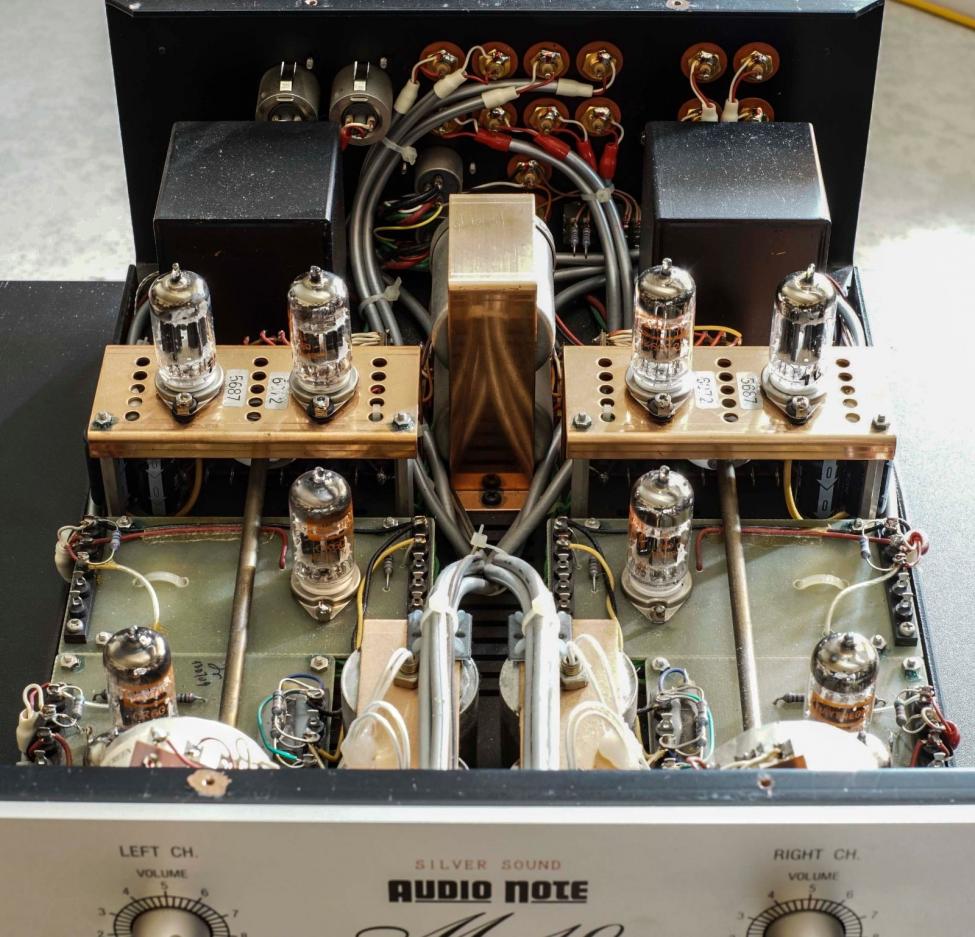
=============================
Audio Note UK M10
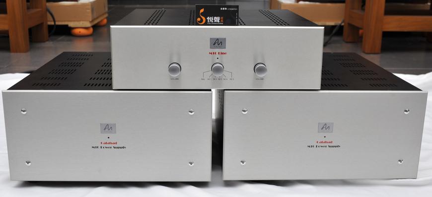
M10 Line Signature
Again, there are TWO different beasts of a preamp called M10. The orginal poster jerrylong posted a schematic of a M10 that was designed by Kondo in Japan, clearly dated in the schematic at 1996. Audio Note UK was formed after that and introduced a preamp that also happened to be called M10. Due to legal issue, Audio Note Japan later renamed the company as Kondo. The two preamps are designed by different people, by different companies. The British company is simply called Audio Note UK.
They are different preamps. ANJP uses 6072 & 5687 tubes and ANUK uses 12AU7 & 6463. Jerrylong needs to decide which preamp he wants to clone. He first posted the Japanese schematic and then jazbo8 posted a quote by Peter Qvortrup of ANUK about their M10 transformer. And then Jerrlong posted a discussion in a Chinese forum about ANUK M6 transformer. All of this only adds to the confusion.
You can go back talking about circuitry and transformers. All I'm saying is that the schematic posted is NOT related to the transformer Peter Qvortrup was talking about.
Please return to your regular programming.
=============================
Audio Note Japan (Kondo era) M10
=============================
Audio Note UK M10
M10 Line Signature
There is no M10 in the Kondo catalogue. All their preamps have no output transformer. They all have cathode follower output.
Kondo Sun made that preamp for marketing reasons as it was against his philosophy as were the 300B SE and other stuff.
With the exception of the Ongaku (that has more than enough power and also is a display of AN Japan/KONDO skills and craftsmanship regarding transformers) all amps are PSE or PP, all preamps have no transformers (except volume attenuator or MC input).
- Home
- Amplifiers
- Tubes / Valves
- Audio Note M10 Clone