Hi Ian, I bought Bridge pi and Chinese amanero usb board,
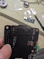
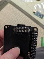
When I pushed pins,Receptor on bridge pi PCB came out.
Then looked holes,there is solder fail and half of hole is filled.
Could I have a change to another PCB?
When I pushed pins,Receptor on bridge pi PCB came out.
Then looked holes,there is solder fail and half of hole is filled.
Could I have a change to another PCB?
Attachments
Remove the resistors in S2 and S6 and then short the pads with solder. Leave the 0 ohm in the S4 as this is just a short anyway - clear?

If I want to scope the xlr output on the OPA861 balanced IV board, how do I go about it.
Will having no load on it be an issue?
Where can I find out more about tools and techniques to measure changes to my system?
Will having no load on it be an issue?
Where can I find out more about tools and techniques to measure changes to my system?
I measure about 75mm, so it would depend so it would depend on How you mount or fasten them in.
Hello,Hi Eduard,
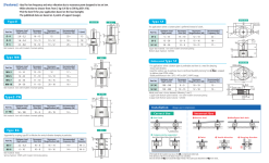
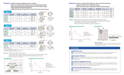
I was looking at the gel vibration damper you provided. Is there a specific item you’re using from that list for your build. Please share which one you’re using.
Best regards
If i did read correctly the weight is when used with 4 dampers. I think i did so then probably you will need to use the A1 or A2 type depending on what is in your stack.. If the bottom board is the UCPI you will need to increase the diameter of the mounting hole but the outer dimensions of the grommet are exceeding the mounting area. The Theta A or B will fit better but they are more expensive but hobby cost money. If you spend loads on the clocks might as well try to makle them work the best they can.
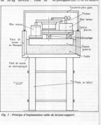
The insulator will connect the board to another item. You can experiment with that item too. The French L''Audiophile magazine published a wooden '' container '' on concrete paws in 1981. In the container there was a kind of marble element buried in 35 kilogrammes of sand that was used as a base for a turntable. No need to copy but sand is cheap. In the USA probably easy to find lead shot.
Maybe you will need to do some experiments to find out where you need to go and how things can be further improved.
Greetings, eduard
Attachments
Hello ,Would the UC-PureIII and the ultracapacitors fit within a 2U (80 mm) height enclosure?
Unless you can use some kind of nylon nuts i would not take the risk. If you have just a very tiny clearance you will need to mount things with decent brackets and no tie raps or similar stuff.
Most enclosures are not that sturdy and with little clearance it is not that difficult to create a short circuit.
Maybe you can make a bigger hole where the nuts could touch the enclosure and then cover that hole with a little piece of metal mounted at 10? millimeter distance by using stand offs. I used this technique several times.
greetings, eduard
Hello,
These caps need burn in to especially if you just will be using a low current. Maybe get a big power resistor and let them do a good exercise.
I support the idea of having the minimal number of interruptions from the cap board to the Q7. NOT sure if you will hear the difference between a ten and a twenty inch cable so i will try to make it 3 inches and just solder at Q7 and probably the same on the other board. I wouldn't worry about the cable gauge. Twist the two cables or not? If it just 3 inches i would not bother.
Many things to try and share.
Greetings,Eduard
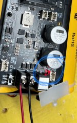
I’m going to hook up to a power brick which is running at about 17v and see if it starts charging. Do I have to de charge it before I hook an actual load up?
D3 lit and nothing blew up and then I unplugged power brick.
D3 lit and nothing blew up and then I unplugged power brick.
Attachments
Last edited:
@eduard
I'm wondering if there is a best way to burn in caps without actually having them in place in audio components? I was told you can use 9-volt batteries and such, but I'd think there would be a better solution? I would imagine that both A/C and D/C devices could be used with a proper rig/setup? I have a benchtop PS that goes up to 30V DC, not sure if I could put parts together for a cap burn-in device? Thanks!
I'm wondering if there is a best way to burn in caps without actually having them in place in audio components? I was told you can use 9-volt batteries and such, but I'd think there would be a better solution? I would imagine that both A/C and D/C devices could be used with a proper rig/setup? I have a benchtop PS that goes up to 30V DC, not sure if I could put parts together for a cap burn-in device? Thanks!
@fusion360guy
You shouldn't have to do anything but let them charge. Those super caps don't have any memory!
You shouldn't have to do anything but let them charge. Those super caps don't have any memory!
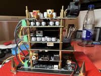
New ES903Q2M Dual Mono MkII board comparison…..


I have to remember to reset my DAC settings via MonitorPiPro as they are probably factory again.
Good job @iancanada
- more noise reduction
- better placement of 3.3v power blocks and optional jumpers to feed left and right from the center block or have 3 separate power input without jumpers
- MCLK inputs on top AND bottom
- enhanced functionality with MonitorPiPro (I don’t know what that is yet stay tuned)
- OPA861 fits better on top. I think the PIN blocks are slightly higher.
I have to remember to reset my DAC settings via MonitorPiPro as they are probably factory again.
Good job @iancanada
Attachments
Hello,
All the info is in the manual. Same like the ucpi it will take some time to charge the caps. During charging there is a selector switched to off position when charging is finished it will be indicated with ucpi . I think ucpure it will be the same.
Instead of connecting the circuit that takes minimal load you could connect a big resistor so it will have shorter periods free from ac because they are drained rather quickly.
Even if they dont have memory they could become "" better "
Good luck, Eduard
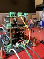
She works. The DAC setting must be stored in MonitorPiPro NVM. It kept what I had even on the new DAC board. Of course everything still sounds stellar.New ES903Q2M Dual Mono MkII board comparison…..
View attachment 1217764
View attachment 1217765
- more noise reduction
- better placement of 3.3v power blocks and optional jumpers to feed left and right from the center block or have 3 separate power input without jumpers
- MCLK inputs on top AND bottom
- enhanced functionality with MonitorPiPro (I don’t know what that is yet stay tuned)
- OPA861 fits better on top. I think the PIN blocks are slightly higher.
I have to remember to reset my DAC settings via MonitorPiPro as they are probably factory again.
Good job @iancanada
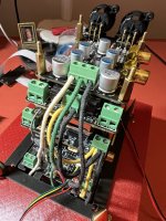
Tomorrow I’ll try and hook up the UCPureIII pack I built. I’m hesitant to do it until I build some kind of case for the UC pack. There too many big metal bolts sticking out to accidentally get shorted out by some household mishaps or something dumb.
I was referring to the burning-in of audio capacitors before installing them. For example: New caps for speakers, instead of running countless hours after assembling a speaker cross-over network, having a device that could run either A/C or D/C voltages for the sole purpose of burning-in X-amount of caps at one time.
If you have a lot of mice, I'd just leave them on the floor! 😂There too many big metal bolts sticking out to accidentally get shorted out by some household mishaps or something dumb.
- Home
- Source & Line
- Digital Line Level
- Asynchronous I2S FIFO project, an ultimate weapon to fight the jitter