I’ve got a 12vdc 3.5A POWER brick right now as a start.
When I get as smart as you all and figure out how to make a toroidal transformer PS, maybe that will be faster !
When I get as smart as you all and figure out how to make a toroidal transformer PS, maybe that will be faster !
you can find in the manual how long it should take. i use ac transformer just one part and i will limit the current to 1.5 a . you will only need one initial charging. after that charging will be automatically and quicker

That's what I'm doing from the start (see one of my recent posts with photos), easy SW resample to different clock "family" and quick AB comparing, track by track.. But since this way I'm getting almost the very same results, I'm rather staying quiet, not to be the only contrarian.After 7 days have you tried going back to the stock clocks? It would be particularly interesting to put in one stock and one Pure to compare the two. Same tune but different sample rates would make for an easy A B comparison of just the clock impact.
Only one thing that comes to my mind is whether the second Accu clock isn't injecting its own noise into the whole system, in which case the benefit of the only one SC-Pure could be partially mitigated .. ? Could someone more knowledgeable answer, whether Is that even remotely possible?
No, the "OE" (Output Enable) pin on the second clock is pulled low, doing so shutting down the oscillator and making its output high impedance. In short, it's not outputting anything.
Manual says “about 1 hour” so I’m just wondering if something is wrong. It’s been 3.5 hours nowyou can find in the manual how long it should take. i use ac transformer just one part and i will limit the current to 1.5 a . you will only need one initial charging. after that charging will be automatically and quicker
The NDK clocks were known to have a significant spread in performance from sample to sample. People were selling specially selected samples at a premium. I wonder how consistent other clocks are. Do you have any info on the performance spread of the SC-Pure, Ian? Thanks.That's what I'm doing from the start (see one of my recent posts with photos), easy SW resample to different clock "family" and quick AB comparing, track by track.. But since this way I'm getting almost the very same results, I'm rather staying quiet, not to be the only contrarian.
Only one thing that comes to my mind is whether the second Accu clock isn't injecting its own noise into the whole system, in which case the benefit of the only one SC-Pure could be partially mitigated .. ? Could someone more knowledgeable answer, whether Is that even remotely possible?
Raspberry 5 Released!!!
https://www.raspberrypi.com/products/raspberry-pi-5/
on Ian stuff, if we plan this latest option, hopefully this will accommodate already existing and happening plans without much limitations.... particularly on the power terms which not it says 5V with 5A @ 27W.
From my end about to start the streamer and dac build plan which needed to analyze more detailed way to plan better....
Many thanks for staying on top of this. I didn't want to but I pre-ordered the RPi5. I was actually trying to hunt down a Compute Module 4 and possibly a Tofu board this week, so I can give up on that pursuit. I will give up on trying to fit a RPi into the current UcPure system and just wait for iterations of UcPure to fit into an RPi @5V/5A.
Fortunately, my Production Chain will still have zero noise and plenty of power with an RPi5 since I run a triple stack of LiFePO4 6.6V -> LPS -> UcConditioner 5V in "Pure" Mode:
J6: UcConditioner 5V output in 2-pin 5.0mm terminal
This output can deliver maximal current higher than 100A, so has to be very careful not to short circuit.
So I'm guessing 5A won't be a problem if the UcConditoner can level up to 100A. The UcPure can't handle the current RPi4 yet, so I would be running the triple stack whether it's RPi4 or RPi5. So I'm hoping end of the year I can just pop in an RPi5 and cross fingers.
I do everything to plug leaks in my "Pure" chain, so zero noise and zero mains thanks to Ian's genius. I don't cut corners or do half measures. So the RPi5 I'm hoping won't be an issue.
I'm actually ahead of schedule now and I can give up on the idea of an RPi-less system now (Save a few grand) since the RPi is still evolving:
I think my best hope is for a RPi5 w/ 16GB RAM which is a few years away.
https://www.diyaudio.com/community/...eapon-to-fight-the-jitter.192465/post-7435705
I wanted to go RPI-less because CPU power is important, but since RPi5 is 2-3 times more powerful than the RPi4 I don't need RPi-less. So this is great news since I run a low latency realtime kernel and I also allocate 3 out of 4 Cortex Cores exclusively for Audio only. I'm currently running 2.4Ghz with RPi4 already, but I'm hoping I can get to 3Ghz with an RPi5 since I run super quiet Noctua fans. My DAC designer, top 3 in the world, stresses Brain Burn-in and how the Humans are sensitive to the tiniest of changes so I try to keep latency super low to near Bare Bone metal levels since even 5 milliseconds can throw things off. For Professional Artist, 5 milliseconds is a dealbreaker. The RPi5 will definitely help with this with the added power.
Anyways, good luck on your build. My projects are done, but I'll try to check in end EOY with RPi5 update. I for one am ecstatic about plugging the RPi5 into my chain since I have no leaks anywhere.
Last edited:
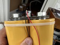
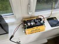
I have an issue. There’s only small voltage across the yellow supercaps. So it’s not charging. And when ON but no pure light in it’s not passing any voltage. Let me know if anyone has suggestions.Manual says “about 1 hour” so I’m just wondering if something is wrong. It’s been 3.5 hours now
Does anyone have actual scope graph comparing input vs output jitter, and blind testing the results?
Otherwise it's a money sink.
Otherwise it's a money sink.
@iancanada refers to jitter tests and phase noise tests in this post https://www.diyaudio.com/community/...eapon-to-fight-the-jitter.192465/post-6289669
Hello,I have an issue. There’s only small voltage across the yellow supercaps. So it’s not charging. And when ON but no pure light in it’s not passing any voltage. Let me know if anyone has suggestions.
Better switch it of!
Check polarity of the wiring. I think manual says something about length of the charging cables.
Caps are not from Ebay or Amazon?
By default it will be charging with 3A but maybe your 3,5 A cant do that. You can easily change the setting to 1,5 A.
You could check the current running with a multimeter.
Greetings, eduard
Thanks eduard. Polarity is good. Length is less than six inches from charger to terminals. UC are from mouser.
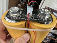
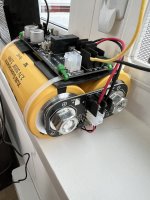
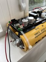
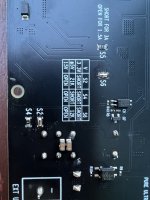
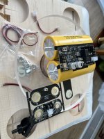
I get no voltage at J7 going to UC pack. So it’s not charging for some reason. Bad board or user error. I’ve read everything six times to Sunday. I have an extra part that isn’t in manual of UC balancer that looks like a spacer to get main board higher up. See pic with edge on view and last parts layout picture. Other than that it looks exactly like the pictures. I’ve check the glass fuse with an ohmeter and there is continuity. Manual says for 3.3v output which I need for fifopiq7 clean side I can use a 9-20dcv laptop ps. Which is what I have. As far as I can tell I’ve followed everything exactly as per manual to get 3.3v output. Issue is board is not supplying charge to caps. Re brick it is 12vdc 5A. Picture added.
I get no voltage at J7 going to UC pack. So it’s not charging for some reason. Bad board or user error. I’ve read everything six times to Sunday. I have an extra part that isn’t in manual of UC balancer that looks like a spacer to get main board higher up. See pic with edge on view and last parts layout picture. Other than that it looks exactly like the pictures. I’ve check the glass fuse with an ohmeter and there is continuity. Manual says for 3.3v output which I need for fifopiq7 clean side I can use a 9-20dcv laptop ps. Which is what I have. As far as I can tell I’ve followed everything exactly as per manual to get 3.3v output. Issue is board is not supplying charge to caps. Re brick it is 12vdc 5A. Picture added.
Attachments

Last edited:
OK. It turns out I am dumb. Everything is ok. It just could take hours to charge up these big yellow scuba tanks!
I will leave it overnight. Note you only get voltage at J7 if you unplug the pack (to check proper voltage for charging).
I will leave it overnight. Note you only get voltage at J7 if you unplug the pack (to check proper voltage for charging).
"When connecting the UC package with switch at the off position, J7 will drop to 0V and will take hours to build up to 3.4V. D8 will keep off until then."
@fusion360guy lets us know the status so we can help. When you are charging the 2 silver capacitors will get warm FYI and if you feel you can please measure the DC voltage across one of those while charging and state the voltage
Thanks eduard. Polarity is good. Length is less than six inches from charger to terminals. UC are from mouser.
I get no voltage at J7 going to UC pack. So it’s not charging for some reason. Bad board or user error. I’ve read everything six times to Sunday. I have an extra part that isn’t in manual of UC balancer that looks like a spacer to get main board higher up. See pic with edge on view and last parts layout picture. Other than that it looks exactly like the pictures. I’ve check the glass fuse with an ohmeter and there is continuity. Manual says for 3.3v output which I need for fifopiq7 clean side I can use a 9-20dcv laptop ps. Which is what I have. As far as I can tell I’ve followed everything exactly as per manual to get 3.3v output. Issue is board is not supplying charge to caps. Re brick it is 12vdc 5A. Picture added.
 Hi, I looked at your image 8412, seems like you have your bridge board connected under.That board is for higher voltage,to connect more capacitors in serie.You created short circuit,hope it helps.
Well spotted! There should be only 1 board at each end of the caps @fusion360guy
Need to remove the bridge board 100%
Need to remove the bridge board 100%
Duh!
Ok. I figured it was to get the main board higher as I had ‘legs’ on bottom side of the board touching the cans. So I put it in there thinking it was to raise things up.Well spotted! There should be only 1 board at each end of the caps @fusion360guy
Need to remove the bridge board 100%
Is it safe to remove and rebuild now without the ‘3rd board’
- Home
- Source & Line
- Digital Line Level
- Asynchronous I2S FIFO project, an ultimate weapon to fight the jitter