of course I cut them all to the same length.Hmmm,,,if the legs not have the exactly same length, the short one will not touch the bottom of the clock adapter, or maybe it is enough connection from the sides surrounding the pins ?
if I put them on a flat surface they don't wobble and are not at an angle but nicely parallel to each other with the same height
Last edited:

My guess is that there is a conductor "on the walls" inside the socket holes, so no matter how long the pins are, as long as they're touching them.
Anyway, @iancanada could shine some light on this matter.
Anyway, @iancanada could shine some light on this matter.
Hello,So the rubber isolator goes under the clocks? Or you can use it with feet? Under the DAC ? I’m waiting for final burn in before I try and ‘fix’ the new clocks.
The '' paws '' of the clocks look rather sturdy so once they are in the vice it will be a tight grip so probably adding a kind of cushion underneath the clock will not change a lot i guess. I presume the clock can be seen as a solid block. If you kind of tickle the clock while it is working will its function be affected?
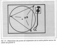
I think because most stacks present here are interconnected by GPIO and stand off i guess the most effective way to create a peaceful surrounding for it will be mounting the lowest board with Taica '' grommets '' with the right weight rating. As you can see in the document the load should be equally spread across the 4 or 3 Taica elements. Maybe you need to add a little extra weight in some area to create an equilibrium.
A bit like Verdier described when using 3 feet positioned around the centre of gravity for his turntable.
You could decide to include the Eatons into the package to be mounted in isolation.
We will have to some test if you want to find the optimum solution.
Greetings, eduard
Attachments
Cool. Now I may have to have a turntable rev 2 ! Or drill other holes and play around. I currently have 4 feet
Ok. This just arrived. I must be graduating to purist. 👨🏫The yellow tanks are bigger than my whole DAC stack 😂😂😂 in pictures they look tiny. Now I know why gabsters case was so big 😎 I better read the manual on this.
How do I discharge them if I need to so I don’t blow anything up! ? In Bell Canada we used to use lightbulbs to discharge central office caps before changing large fuses so they wouldn’t blow.
underneath you see my in progress turntable project! Which will eventually plug into this DAC (I know - not a purist move).
I am going to await the manual that will surely follow on the formal SC-Pure release which I’m sure will deal with a lot of these questions. Follow manufacturers directions - step one for me ! For now the direction that came to me upon ordering was “don’t reverse them” 😎My guess is that there is a conductor "on the walls" inside the socket holes, so no matter how long the pins are, as long as they're touching them.
Anyway, @iancanada could shine some light on this matter.
OK. I found this in the UCBalancer manual. It also says on the EATON google results that "Supercapacitors are transported fully discharged. "Ok. This just arrived. I must be graduating to purist. 👨🏫The yellow tanks are bigger than my whole DAC stack 😂😂😂 in pictures they look tiny. Now I know why gabsters case was so big 😎 I better read the manual on this.
How do I discharge them if I need to so I don’t blow anything up! ? In Bell Canada we used to use lightbulbs to discharge central office caps before changing large fuses so they wouldn’t blow.
underneath you see my in progress turntable project! Which will eventually plug into this DAC (I know - not a purist move).
This is such a journey!
Question: is there a safe easy way to change UCPureIII voltage from default of 5v to 3.3v? I think I got the wrong version.
I see the designation on back to short 3 terminal where there are surface mount resistors but there are not shorting straps on either side of board.
When I read the voltages with voltmeter they more closely correspond to 5V.
I see the designation on back to short 3 terminal where there are surface mount resistors but there are not shorting straps on either side of board.
When I read the voltages with voltmeter they more closely correspond to 5V.
yes, clearly an improvement in sound. the pins were also very long, perhaps 4 to 5 millimeters above the bottom of the socket. Previously the stereo image was a bit stuck in the middle and not really a nice open sound. Whether the improvement has been due to the length of pins or whether they are now flat on the socket... I wouldn't know.I thought so,if not, no sound i guess. Any change in sound ?
For the readers, I am talking about the accusilcon here.
Last edited:
Hello,
So clocks should wear flip flops and not high heels?
Greetings,Eduard
P.s maybe a to long connection will work as an aerial
So clocks should wear flip flops and not high heels?
Greetings,Eduard
P.s maybe a to long connection will work as an aerial
The answer is to short the resistor DIY style with solder although the manual calls them jumpers. So to me it was confusing. Once you do this it’s probably not easy to go back to another config.Question: is there a safe easy way to change UCPureIII voltage from default of 5v to 3.3v? I think I got the wrong version.
I see the designation on back to short 3 terminal where there are surface mount resistors but there are not shorting straps on either side of board.
When I read the voltages with voltmeter they more closely correspond to 5V.
Correct, replace the smd resistor with a jumper, after that it’s not easy going back to 5v. Tiny stuff.
Hi Eduard,Hello,
He is talking about the accusilon clocks.
If you look at the clock like you look at a cartridge using lots of imagination.you will understand that you will need more than amazon spikes to get optimum results.
Greetings,Eduard
I was looking at the gel vibration damper you provided. Is there a specific item you’re using from that list for your build. Please share which one you’re using.
Best regards
Hello,Hi Eduard,
I was looking at the gel vibration damper you provided. Is there a specific item you’re using from that list for your build. Please share which one you’re using.
Best regards
You will have to check the document attached and look for grommets which have appropriate weight specs.
Right now at work put i can make printscreen when home again.
There are just a handful of items useful for the stack because of the low weight.
Greetings Eduard
Anyone happen to have a photo. I have heard to use jumpers and I have heard ‘solder balls’. I guess just short the resistor by joining the two ends?Correct, replace the smd resistor with a jumper, after that it’s not easy going back to 5v. Tiny stuff.
You just short the pads with solder - the gap is small so very easy to do.....

.....of course if you want 3.3v you remove the resistors and short the pads with solder
.....of course if you want 3.3v you remove the resistors and short the pads with solder
- Home
- Source & Line
- Digital Line Level
- Asynchronous I2S FIFO project, an ultimate weapon to fight the jitter