@gionag
Basically, phase jitter is the integration of the phase noise plot. Phase jitter equals to time jitter when integrating over the whole bandwidth. Phase noise and jitter can be translated in between.
https://www.eetimes.com/phase-noise-and-jitter-a-primer-for-digital-designers/
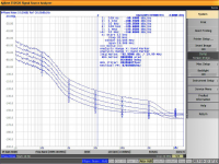
RcClockPi SCK was re-clocked by MCLK, so it's phase noise tendency will mainly follow the MCLK. To estimate the phase noise from the jitter, we need to shift the MCLK phase noise plot until the integration result equals to the RMS jitter. Have to use the integration bandwidth as wide as possible to make the result more accurate (I use 0.1Hz to 1MHz). The estimated phase noise floor could be better than a real phase noise analyzer because the phase noise calculator doesn't have a physical input noise floor limitation. However the close-in phase noise estimated result will be more accurate because the close-in phase noise weights much higher than the noise floor to the final phase jitter result.
Regards,
Ian
... i don't really want to argue because my grasp of the topic is surely inferior to yours, but
Analog Devices says the contrary, i remeber i had red a FAQ on their site.
searched back again and reported here for convenience :
Q : If jitter can be calculated from phase noise measurements, is it possible to calculate phase noise from jitter numbers?
A : No. Only the total integrated phase noise power over the bandwidth of integration can be calculated from the jitter number. The shape of the phase noise spectrum, and the offset limits used, are lost in the calculation of the phase jitter.
If jitter can be calculated from phase noise measurements is it possible to calculate phase noise from jitter numbers? | Analog Devices
... is it opinable ?
Last edited:
Measuring phase noise with an oscilloscope: Measuring Phase Noise with a Real Time Sampling Oscilloscope. - Technical Support Knowledge Center Open
Measuring phase noise with an oscilloscope: Measuring Phase Noise with a Real Time Sampling Oscilloscope. - Technical Support Knowledge Center Open
and that's fine, i don't know to what extent, but surely you can measure (or extract) phase noise plot with an oscilloscope...
i was just saying that from my knowledge is impossibile to reconstruct a phase noise envelope from a pure jitter number.
but i am sure i am missing a big piece of information 🙂
@InspectorGadget
No, it's a forked project. No FiFo buffer, but focus will be on a PCIe USB card instead. I will only use Ian's battery power supply for that project and will scale with more bridged MKIII as needed. I'm also going USB optical instead of toslink. Since it's another project, it's probably off-topic for this thread, so will end it here. I just wanted to give a general idea of alternative 12V PC solutions. My DAC doesn't really need reclocking if I go USB. I will be running USB optical for desktop and TOSLINK for portable.
I'm basically trying to build a battery-powered poor man's $30,000 Taiko Extreme:
SGM Extreme Music Server – Taiko Audio
The Extreme likely runs a Sage dual Xeon C621 motherboard, but that's another rabbit hole and it runs on mains. Maybe that can be a future project, but for now I'll be happy with a battery-powered motherboard with an i9/i7 CPU. I believe at the heart of the Sage is a master clock that controls all processing functions. The Extreme likely has a custom clock to replace the stock clock for it's magic. It would be pretty sweet to put a Andrea Mori clock at the heart of the Sage motherboard. Maybe one day.
I'm already overjoyed with my portable Q3, so I have no motivation to build a duplicate Q3 system for desktop. I do wish I was able to utilise the 26650 w/tabs for portable, but otherwise super happy with this setup already. With a RCP and upgraded clock, I'll be set on this Q3 end. It makes no sense for me to duplicate this effort and build a desktop Q3 so I'm trying to go 12V PC. I want to avoid any additional conversions with 12V PC, so will be listening straight out of PCIe USB card via USB optical via Uptone USPCB.
I'll be running AudioLinux or Euphony for the 12V PC build.
Let's not detour the thread anymore with 12V PC, so hope this clears things up. I'm not mixing FiFo Buffer with low latency realtime kernel 12V PC. Separate Projects.
@A123, so you are going to start on a high power, battery powered board, with low latency and added fifo buffer? You'll excuse me if I say that chain contains a lot of contradictions.
No, it's a forked project. No FiFo buffer, but focus will be on a PCIe USB card instead. I will only use Ian's battery power supply for that project and will scale with more bridged MKIII as needed. I'm also going USB optical instead of toslink. Since it's another project, it's probably off-topic for this thread, so will end it here. I just wanted to give a general idea of alternative 12V PC solutions. My DAC doesn't really need reclocking if I go USB. I will be running USB optical for desktop and TOSLINK for portable.
I'm basically trying to build a battery-powered poor man's $30,000 Taiko Extreme:
SGM Extreme Music Server – Taiko Audio
The Extreme likely runs a Sage dual Xeon C621 motherboard, but that's another rabbit hole and it runs on mains. Maybe that can be a future project, but for now I'll be happy with a battery-powered motherboard with an i9/i7 CPU. I believe at the heart of the Sage is a master clock that controls all processing functions. The Extreme likely has a custom clock to replace the stock clock for it's magic. It would be pretty sweet to put a Andrea Mori clock at the heart of the Sage motherboard. Maybe one day.
I'm already overjoyed with my portable Q3, so I have no motivation to build a duplicate Q3 system for desktop. I do wish I was able to utilise the 26650 w/tabs for portable, but otherwise super happy with this setup already. With a RCP and upgraded clock, I'll be set on this Q3 end. It makes no sense for me to duplicate this effort and build a desktop Q3 so I'm trying to go 12V PC. I want to avoid any additional conversions with 12V PC, so will be listening straight out of PCIe USB card via USB optical via Uptone USPCB.
I'll be running AudioLinux or Euphony for the 12V PC build.
Let's not detour the thread anymore with 12V PC, so hope this clears things up. I'm not mixing FiFo Buffer with low latency realtime kernel 12V PC. Separate Projects.
Last edited:
@eduard
I have a good news for you.
Just installed the two Andrea's sine to square converter boards to the FifoPi Q3 and ReClockPi. ReClockPi reserves a window opening for upgrading XOs. So they perfectly fit together without any problem.
ReClockPi uses four layers PCB. It also has an additional ground layer working as a shield similar to a ShieldPi to reduce EMI noise into the DAC or other sensitive audio devices.
Please find the attached picture for more details.

ReClockPiFifoPiSinSquare by Ian, on Flickr
Ian
I have a good news for you.
Just installed the two Andrea's sine to square converter boards to the FifoPi Q3 and ReClockPi. ReClockPi reserves a window opening for upgrading XOs. So they perfectly fit together without any problem.
ReClockPi uses four layers PCB. It also has an additional ground layer working as a shield similar to a ShieldPi to reduce EMI noise into the DAC or other sensitive audio devices.
Please find the attached picture for more details.
ReClockPiFifoPiSinSquare by Ian, on Flickr
Ian
Last edited:
Hello Ian,
Andrea and me just arranged that he will send me an invoice for the parts related to the clocks.
I will probably order your circuits in France. When will the reclockpi be available or will ordering this one be quicker in Canada?
Greetings, Eduard
Andrea and me just arranged that he will send me an invoice for the parts related to the clocks.
I will probably order your circuits in France. When will the reclockpi be available or will ordering this one be quicker in Canada?
Greetings, Eduard
From the photo seems that the sts-dx's sma connector don't have enough clearance to allow an sma connector to screw in... Have you tested a cable over it ?@eduard
I have a good news for you.
Just installed the two Andrea's sine to square converter boards to the FifoPi Q3 and ReClockPi. ReClockPi reserves a window opening for upgrading XOs. So they perfectly fit together without any problem.
ReClockPi uses four layers PCB. It also has an additional ground layer working as a shield similar to a ShieldPi to reduce EMI noise into the DAC or other sensitive audio devices.
Please find the attached picture for more details.
https://flic.kr/p/2kV6sFD
ReClockPiFifoPiSinSquare by Ian, on Flickr
Ian
Hi Ian !
I am looking forward to your ReClockPi. The stack still has enough room for it . 🙂
The current includes input and output via HDMI .
(1): Pi2 + ReceiverPi + FifoQ3 + TransportPi + AD1865R .
(2): Pi4 + HDMIPi + I2S / DSD / ReceiverPi .


Player : Smpd + Roonbidge . 🙁
symphonic-mpd
ホーム | symphonic-mpd
20210127 161003 - YouTube
Last edited:
@linh0983
Your project looks very nice. Very well finished system. Thank you for sharing.
ReClockPi would be good for your system for more upgrade. It's very easy to use, just install it on top of the FifoPi with a u.fl MCLK cable connected in between. Signal quality will be improved. Noise over the logic levels will be reduced. I'm working very hard now to make it available soon.
BTW, what is the SMPD player?
Regards,
Ian
With the RCP soon-to-be-release and the small possibility of a Andrea Mori 5.6448 MHz clock, I decided to cancel my 12V PC build project for good for now.
Also, I have too many parts laying around so I probably should complete before tackling a new project.
My solid core 18AWG silver power wires cost more than the dozen Super Caps, so all would go to a double-whammy hit waste if I went PC build.
Also, I have too many parts laying around so I probably should complete before tackling a new project.
My solid core 18AWG silver power wires cost more than the dozen Super Caps, so all would go to a double-whammy hit waste if I went PC build.
Last edited:
Since this is my first DIY project, I didn't want to take any shortcuts. Especially as the DIY veterans here recommend a proper gauge wire.
If they offered 12AWG-16AWG Solid Core Silver I may have considered. But the 18AWG was originally for portable, but it should be fine for desktop too.

Neotech Solid UPOCC Silver in Teflon 18 AWG Blue, Sonic Craft
I believe SonicCraft is a sponsor or Member of the Trade for this site.
I went with these because if I order a Ghent Audio DC solid core cooper one day, is should synergise well as it's the same Neotech solid core brand. Unfortunately, they don't offer Silver.
ghentaudio --- DC-7N16C Neotech UPOCC 7N Copper 16AWG DC(JSSG360) Cable

If they offered 12AWG-16AWG Solid Core Silver I may have considered. But the 18AWG was originally for portable, but it should be fine for desktop too.
Neotech Solid UPOCC Silver in Teflon 18 AWG Blue, Sonic Craft
I believe SonicCraft is a sponsor or Member of the Trade for this site.
I went with these because if I order a Ghent Audio DC solid core cooper one day, is should synergise well as it's the same Neotech solid core brand. Unfortunately, they don't offer Silver.
ghentaudio --- DC-7N16C Neotech UPOCC 7N Copper 16AWG DC(JSSG360) Cable
Last edited:
@A123
The solid silver wire looks promising. Can I make a finger ring with it? 🙂
Maybe I should consider buy some ...
Ian
The solid silver wire looks promising. Can I make a finger ring with it? 🙂
Maybe I should consider buy some ...
Ian
... i don't really want to argue because my grasp of the topic is surely inferior to yours, but
Analog Devices says the contrary, i remeber i had red a FAQ on their site.
searched back again and reported here for convenience :
Q : If jitter can be calculated from phase noise measurements, is it possible to calculate phase noise from jitter numbers?
A : No. Only the total integrated phase noise power over the bandwidth of integration can be calculated from the jitter number. The shape of the phase noise spectrum, and the offset limits used, are lost in the calculation of the phase jitter.
If jitter can be calculated from phase noise measurements is it possible to calculate phase noise from jitter numbers? | Analog Devices
... is it opinable ?
@gionag
I understand what’s your concern. I thought I described the principle. Now just let me make it more clear.
MCLK is the parent clock. SCK is the child clock which was divided from the parent MCLK by a high speed synchronized logic and finally generated at the last flip-flops re-clock stage. I used a 22. 5792 MHz CCHD957 as the MCLK in the test, so that SCK for 88.2 KHz music was the MCLK divided by 4.
There is a 20log(N) rule which means If the carrier frequency of a clock is divided down by a factor of N then we expect the phase noise to decrease by 20log(N). So each time MCLK is divided by 2, the phase noise plot will be improved by 6dBc/Hz. The whole phase noise plot will be shifted -6dB down with integration RMS jitter kept the same.
Timing 101: The Case of the Jitterier Divided-Down Clock
However in the real world, there is no ideal divider. A good high speed discrete flip-flop chip normally has around 1ps additive RMS jitter (can be better with carefully designed PCB trace and really good low noise power supply). So, the phase noise plot of the child clock will be traded off and the shift will be less than 6dB. That’s why we need to estimate the phase noise from jitter to figure out what's the real case and to confirm.
With this principle, to estimate the phase noise from jitter, we need to shift the MCLK phase noise plot lower to make sure the integration of RMS phase jitter is equal to the RMS time jitter. Have to use the integration bandwidth as wide as possible to make the result more accurate (I use 0.1Hz to 1MHz). If necessary, make some compensation to the noise floor.
The disadvantage of this method is that the estimated phase noise floor could be better than a real phase noise analyzer because the phase noise calculator doesn't have a physical input noise limitation. However the good thing is that the close-in phase noise estimated result will be more accurate because the close-in phase noise weights much higher than the noise floor to the final RMS phase jitter result. Yes, there is no perfect way to get the phase noise from time jitter. But for me I think this method is pretty acceptable.
Regards,
Ian
Attachments
Last edited:
🙂 You may have to double loop for a "My Precious" ring.
If I ever finish my project, I can snail mail you any spare parts I have left (Neotech, Keystone, etc.). But that's month's away and I'm using solid core for UcHybrids to MKIII as I bought Molex connectors, so not sure I will have any left.
If you do decide to order, you can contact Sonic Craft here:
https://www.diyaudio.com/forums/sonic-craft/
Maybe they can give you a discount since you are somewhat "colleagues". I got mine during the holiday sale for around $25/ft.
They may be hard to find in Canada. PC only down to 20AWG:
Neotech Silver PTFE Solid Hook-Up Wire
Last edited:
Ian....is the Fifo pi clock input 5v tolerant.
I am just about to trial Andrea's TWTMC PPG and I need to add a 100r to his board if not.
I am just about to trial Andrea's TWTMC PPG and I need to add a 100r to his board if not.
Thanks Ian. I added the 100R in the meantime just in case but good to know.
Looking forward to trying your Reclock Pi
Looking forward to trying your Reclock Pi
@jimk04
Yes, FifoPi inputs are 5V tolerant.
For real? And the ReclockPi too?
I got myself a Kali Reclocker only because I didn't want to introduce a 3.3V PSU just for these HATs (both the RPi and my DAC take 5V). But if both FifoPi Q3 and ReclockPi take 5V, I know what I'll be ordering soon!
- Home
- Source & Line
- Digital Line Level
- Asynchronous I2S FIFO project, an ultimate weapon to fight the jitter