Yes, you should. You may try to place the I2C isolator at the empty space. You can source it from digikey.
Ian
Ian
Please advise the digikey part no. for the 2 pins plug and socket for power connection on clock board.
These wouldnt drop below 3.45 till about 1/2 way through their charge, sits on 3.50->3.40 for ages and at ~90% discharge they are still sitting about 3.2. Mine wouldnt drop off that steeply under a 10A load.
they might be lifepo4, but probably not Nanophosphate. what are you using to cut off the voltage, till the battery board is ready that is? could you have damaged them with repeated deep discharge, or have they always been like that?
they might be lifepo4, but probably not Nanophosphate. what are you using to cut off the voltage, till the battery board is ready that is? could you have damaged them with repeated deep discharge, or have they always been like that?
Ian
Please advise the digikey part no. for the 2 pins plug and socket for power connection on clock board.
They are 2pin JST PH series, I believe, 455-1734-1-ND - I don't have the connector in hand or a clock board so I could be wrong, but if in doubt, check the BOM for the battery board, I think Ian would have used the same connectors there.
These wouldnt drop below 3.45 till about 1/2 way through their charge, sits on 3.50->3.40 for ages and at ~90% discharge they are still sitting about 3.2. Mine wouldnt drop off that steeply under a 10A load.
they might be lifepo4, but probably not Nanophosphate. what are you using to cut off the voltage, till the battery board is ready that is? could you have damaged them with repeated deep discharge, or have they always been like that?
As I still testing my setup, haven't considered the cut off yet. The batteries are new and have been recharged less than 10 times. Only been deep discharged twice.
Waiting for Ian's battery board to safe my life again😀
They are 2pin JST PH series, I believe, 455-1734-1-ND - I don't have the connector in hand or a clock board so I could be wrong, but if in doubt, check the BOM for the battery board, I think Ian would have used the same connectors there.
Thanks hochopeper. Found them in Digikey.
I'd get Ian to confirm that, it's just an educated guess. I went and checked the BOM for the battery monitor board and it is a through hole version, so not the same as I had first thought.
They are 2pin JST PH series, I believe, 455-1734-1-ND - I don't have the connector in hand or a clock board so I could be wrong, but if in doubt, check the BOM for the battery board, I think Ian would have used the same connectors there.
Thanks hochopeper, for the P/N of SMD version,
455-1165-ND
455-1127-2-ND
455-1704-ND
Ian
I guess i'll take that bow nowAs I said you can make it🙂. Did your hand survive from the hot air 😀.
I like the isolator board, it makes the grounding design much easier for a DAC to get rid of ground loop. The clock should always be treated as an analog part for a DAC. The isolator board makes them together.
Ian


lol
Last edited:
 was a good suggestion mate!
I want to know what bigpandahk has planned now he's the only guy apart from Ian with more than one of those isol boards!
I2C isolator for FIFO isolator board, Si8605
To provide I2C isolation for ESS9018, as well as optional serial port isolation for later on Si570 clock board, I recommend:
SI8605AD-B-IS, 336-2053-5-ND
It's pin to pin compatible with the reserved footprint on the FIFO isolator PCB, with providing both I2C isolation and serial port isolation at same time.
That would be a good news for those who use external controller for ESS9018 DAC.
Ian
Attachments
To provide I2C isolation for ESS9018, as well as optional serial port isolation for later on Si570 clock board, I recommend:
SI8605AD-B-IS, 336-2053-5-ND
It's pin to pin compatible with the reserved footprint on the FIFO isolator PCB, with providing both I2C isolation and serial port isolation at same time.
That would be a good news for those who use external controller for ESS9018 DAC.
Ian
Great suggestion, Ian. I can use the second isolator board for the DSD input from Teleporter. Still have two IC positions to use😀
what about the additive jitter? the reason I suggested the isolator for where it is, is because its directly reclocked afterwards, with DSD it wont be, but I suppose it will mean the whole system is isolated and you will rely on ESS jitter rejection
what about the additive jitter? the reason I suggested the isolator for where it is, is because its directly reclocked afterwards, with DSD it wont be, but I suppose it will mean the whole system is isolated and you will rely on ESS jitter rejection
That's indeed.
what about the additive jitter? the reason I suggested the isolator for where it is, is because its directly reclocked afterwards, with DSD it wont be, but I suppose it will mean the whole system is isolated and you will rely on ESS jitter rejection
That's also why I think the isolator is less advantageous if you've got the PCM converter in your system after the clock board, or does the PCM conversion happen before the clock board?
as I understand it, its kinda in parallel with the clock board, replacing the flipflops that are there now for i2s and clocked by the clean MCLK, so the isolator will still be useful
As the FIFO is not DSD compatible, so the DSD shall be directly connected to BIII using the OTTO II for selection. I agree that Isolation may not be a good idea.
well you will want to switch ground and signal with the DSD so its completely unconnected to the dac when not in use; otherwise all the trouble of isolating i2s will be undone
I am also using LiFEPO4 battery without any problem with both clock and FIFO. 6.6V is only when the battery is fully charged and will drop below 6.5V in very short time.
Hi Bigpandahk,
My friend bough one of this LiPO for me to power my dac, he basically use these kind of battery for RC so, extream fast discharging is a must, a 50C battery cannot discharged in only few minutes in the field.
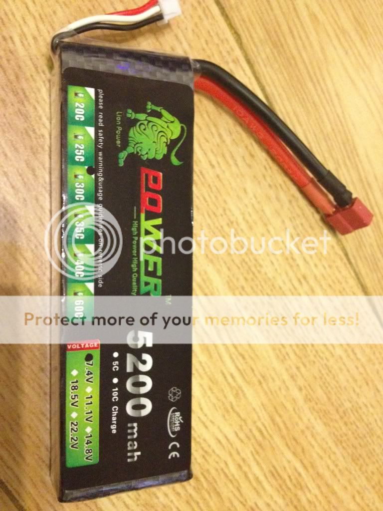
This newly charged one read 8.38V rated at 5700maH 30C.
My Old one rated at 5800maH 50C, after 10 hours usage, it still reads 7.69V. I had use it for 3 weeks for about 105 hours and it read 6.8V. You should get it change up again when it fell below 6.3V, it is a safe margin.

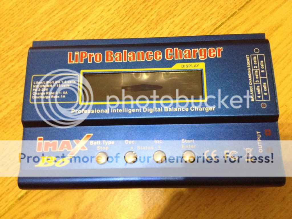
Charge it using this
- Home
- Source & Line
- Digital Line Level
- Asynchronous I2S FIFO project, an ultimate weapon to fight the jitter