That's nice. The I2S from the Toslink board still share its ground via the uf-L cable from the beneath board (FIFO Pi?) ? No isolation there as not needed, i.e. naturally made by the Toslink ?
What about the oled design made by John from ECDESIGN ? Cab it be superseeded on that ?
The compact size with the A123 is very cool 🙂.
Thanks. @iancanada would be better to answer this question. @iancanada, the I2S signal travels from the Q3 to the TransportPi via GPIO? The u.fl cable from the Q3 to TransportPi handles the clock functions?
Sorry, I completely forgot since I'm at the end of the implementing stage instead of the researching stage.
Is the ground shared with u.fl and I2S? Does toslink naturally decouple or is there some decoupling after the I2S signal is passed by the RPi and before it's transformed to an optical signal?
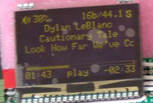
It's not ECDESIGN. I may have trouble getting the German OLED working. the endpoints are very fragile and a ground tip was lost. I got cheap and didn't order the pin holder attachment and worked directly on the OLED board. Once I receive the pin holder attachment, I will try again. I did get the cheap off the shelf OLEDs to work, but the German OLED is more complicated. I attached a photo of the German OLED.
If I can get the German OLED working, I'll post. But it may be a lost cause given the ground tip broke off.
Attachments
The RPi Compute Module 4 with a custom board could be a way toward minimization in your case. CM4 has an eMMC option too. Kicad files for the official CM4 IO board are available, making a custom board design much easier.
You're right. I just took a look and there are some amazing projects.
It's all official RPi too! When I think of the IO board, I just think of a big clunky development board. When I think of anything CAD-related, I think third-party.
But Digikey handles these official RPi orders, so if I a run into a project similar to a A+ maybe I will try out an order.
I noticed a competitor streamer CM4 Kicad project out there so on the right track.
Thanks. @iancanada would be better to answer this question. @iancanada, the I2S signal travels from the Q3 to the TransportPi via GPIO? The u.fl cable from the Q3 to TransportPi handles the clock functions?
Sorry, I completely forgot since I'm at the end of the implementing stage instead of the researching stage.
Is the ground shared with u.fl and I2S? Does toslink naturally decouple or is there some decoupling after the I2S signal is passed by the RPi and before it's transformed to an optical signal?
It's not ECDESIGN. I may have trouble getting the German OLED working. the endpoints are very fragile and a ground tip was lost. I got cheap and didn't order the pin holder attachment and worked directly on the OLED board. Once I receive the pin holder attachment, I will try again. I did get the cheap off the shelf OLEDs to work, but the German OLED is more complicated. I attached a photo of the German OLED.
If I can get the German OLED working, I'll post. But it may be a lost cause given the ground tip broke off.
@A123
FifoPi Q3 feeds I2S/DSD signals to TransportPi through GPIO.
The MCLK to TransportPi will be through the u.fl cable.
u.fl cables share the ground with GPIO. But high frequency MCLK will be mainly turreted from the coaxial cable ground.
The S/PDIF output in RAC has an digital audio transformer so it's isolated for sure. The OPT output will be naturally isolated.
Please let me know if you have more questions.
Regards,
Ian
Many Thanks Ian!
@diyiggy, I hope I re-phrased your questions properly and this answers the questions you had. It helped me to understand a little bit more about it in the process since I'm just an end SQ user.
Trying to get the most out of TWTMC clocks for FifoPi system (7)
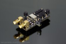
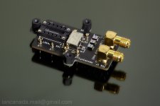
SinePi prototype PCB
Picture1 and picture2
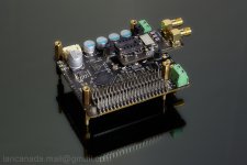
SinePi PCB assembling
Picture3
Install a SindPi into a FifoPi. SinePi is a one piece PCB architecture with full 8 PINs connected to the FifoPi XO sockets. Fit very well.
Picture4
SinePi works with ReClockPi and FifoPi and two TWTMC sine clocks. The right angle SMA RF connectors will connect coaxial cables from the right side of the PCB for a better integration.
SinePi also has three mounting holes for additional nylon standoffs to keep the SinePi very solid at the position without any loose.
Picture5
SinePi runs at half sine mode with one external sine clock and one local square clock.
Sine to square converter is a very sensitive circuit. AM noise is very easy to be modulated into time jitter of the square wave outputs. To achieve best possible low noise performance, SinePi uses a four-layer double side mounted PCB. It has a very carefully designed PCB layout with all impedance controlled clock traces to optimize signal quality. All resistors are metal film for lowest possible noise. All capacitors are NP0, organic Polymer, film and big size X7R to ensure lowest possible power supply noise under mechanical vibration by reducing the piezoelectric effect. The two inner layers work as whole pieces of ground shield plate to provide a continuous returning path for clock signal to reduce ground bounce noise.
More testing results will be posted soon.
Other links:
1.https://www.diyaudio.com/forums/dig...mate-weapon-fight-jitter-657.html#post6668751
2.https://www.diyaudio.com/forums/dig...mate-weapon-fight-jitter-660.html#post6671042
3.https://www.diyaudio.com/forums/dig...mate-weapon-fight-jitter-662.html#post6675622
4.https://www.diyaudio.com/forums/dig...mate-weapon-fight-jitter-664.html#post6678025
5.https://www.diyaudio.com/forums/dig...mate-weapon-fight-jitter-673.html#post6686256
6.https://www.diyaudio.com/forums/dig...mate-weapon-fight-jitter-677.html#post6690153
SinePi prototype PCB
Picture1 and picture2
SinePi PCB assembling
Picture3
Install a SindPi into a FifoPi. SinePi is a one piece PCB architecture with full 8 PINs connected to the FifoPi XO sockets. Fit very well.
Picture4
SinePi works with ReClockPi and FifoPi and two TWTMC sine clocks. The right angle SMA RF connectors will connect coaxial cables from the right side of the PCB for a better integration.
SinePi also has three mounting holes for additional nylon standoffs to keep the SinePi very solid at the position without any loose.
Picture5
SinePi runs at half sine mode with one external sine clock and one local square clock.
Sine to square converter is a very sensitive circuit. AM noise is very easy to be modulated into time jitter of the square wave outputs. To achieve best possible low noise performance, SinePi uses a four-layer double side mounted PCB. It has a very carefully designed PCB layout with all impedance controlled clock traces to optimize signal quality. All resistors are metal film for lowest possible noise. All capacitors are NP0, organic Polymer, film and big size X7R to ensure lowest possible power supply noise under mechanical vibration by reducing the piezoelectric effect. The two inner layers work as whole pieces of ground shield plate to provide a continuous returning path for clock signal to reduce ground bounce noise.
More testing results will be posted soon.
Other links:
1.https://www.diyaudio.com/forums/dig...mate-weapon-fight-jitter-657.html#post6668751
2.https://www.diyaudio.com/forums/dig...mate-weapon-fight-jitter-660.html#post6671042
3.https://www.diyaudio.com/forums/dig...mate-weapon-fight-jitter-662.html#post6675622
4.https://www.diyaudio.com/forums/dig...mate-weapon-fight-jitter-664.html#post6678025
5.https://www.diyaudio.com/forums/dig...mate-weapon-fight-jitter-673.html#post6686256
6.https://www.diyaudio.com/forums/dig...mate-weapon-fight-jitter-677.html#post6690153
Attachments


Last edited:
excellent job Ian. Now we look forward how it measures AND sounds ;-) (I will post more clock blog stuff later today I hope - test 3 is done, need to write it up)
On a vaguely related topic: you always put many links to certain posts at the bottom.
When I click on them they always bring me back to post #1... Is that only me?
I just read the link and look for the post number and go their manually, but that kind of defeats the purpose of a link, right ? 😀
On a vaguely related topic: you always put many links to certain posts at the bottom.
When I click on them they always bring me back to post #1... Is that only me?
I just read the link and look for the post number and go their manually, but that kind of defeats the purpose of a link, right ? 😀
Now that both my countries are kicked out of the European Championships, time for hobby again! I just published my clock test 3 on my blog website…
The Clock Tests (part 3) - DDDAC
The Clock Tests (part 3) - DDDAC
Hi Ian,
I love the Sinepi design! I volunteer as beta tester!
I am getting tired of the loose fit of Andrea’s squarer as I use 4 of his latest clocks and some doublers and like to experiment😉
I love the Sinepi design! I volunteer as beta tester!
I am getting tired of the loose fit of Andrea’s squarer as I use 4 of his latest clocks and some doublers and like to experiment😉
@Supersurfer
That's great. I'll take it into consideration.
What DAC are you using for your setup?
Regards,
Ian
That's great. I'll take it into consideration.
What DAC are you using for your setup?
Regards,
Ian
Hi Ian, I am also seriously interested in purchasing this once ready.
I love the design and connectivity which will work better with the reclockPi where the clock connections are at the side
Thanks
Simon
I love the design and connectivity which will work better with the reclockPi where the clock connections are at the side
Thanks
Simon
@Supersurfer
That's great. I'll take it into consideration.
What DAC are you using for your setup?
Regards,
Ian
Hi Ian,
I have a 4 board modified dddac, 2 TDA1541A-S1 dacs (one in simultanous mode and building a second board to use it in balanced mode) and some of your ess dacs (but you know these I believe 😀)
My source is a USBridge signature with your fifopi Q3 and reclockpi (which is a nice upgrade!) with UcConditioners in the PS.
Clocks are the new drixo SC-cut 5-6-22-24mhz. Currently powered with one of your battery boards.
Regards,
- Home
- Source & Line
- Digital Line Level
- Asynchronous I2S FIFO project, an ultimate weapon to fight the jitter