That's a serious problem I have with wine : It adds jitter after few glasses ! 😀
It works like a low pass filter : phase being worse as the ('drinking) frequence increases, making all slower ! Uh...
It works like a low pass filter : phase being worse as the ('drinking) frequence increases, making all slower ! Uh...
Last edited:
Trying to get the most out of TWTMC clocks for FifoPi system (6)
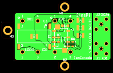
Design SinePi, a possible better sine to square converter for FifoPi
Design ideas:
1. One piece PCB architecture with full 8 pins connecting to the FifoPi XO sockets
2. Discrete sine to square converter to achieve best possible low jitter performance and good low noise signal quality
3. Support both full sine mode with two external sine inputs and half sine mode with one local clock one external sine input
4. Flawlessly works with FifoPi Q1,Q2 and Q3,
5. Disabling the unselected clocks by the on-board relay switches. Can be in three different configurations:
A: No relay for FifoPi Q3
B: Standard relay for FifoPi Q1,Q2 and Q3
C: RF relay for FifoPi Q1,Q2 and Q3
6. Enhanced NP0 and film capacitors decoupling networks to ensure lowest possible power supply noise under mechanical vibration by eliminating piezoelectric effect.
7. Right angle SMA RF sine input connectors for better system integration
8. Three mounting holes for more reliable mechanical supports
9. 50 ohm output impedance with source series termination resistors
10. Input sine clock amplitude range: 0.5V - 5V Vpp in 50 ohm termination
11. Input sine clock frequency range: 1-150MHz
PCB design was finished. Prototype will be ready for testing in two weeks.
Other links
1.https://www.diyaudio.com/forums/dig...mate-weapon-fight-jitter-657.html#post6668751
2.https://www.diyaudio.com/forums/dig...mate-weapon-fight-jitter-660.html#post6671042
3.https://www.diyaudio.com/forums/dig...mate-weapon-fight-jitter-662.html#post6675622
4.https://www.diyaudio.com/forums/dig...mate-weapon-fight-jitter-664.html#post6678025
5.https://www.diyaudio.com/forums/dig...mate-weapon-fight-jitter-673.html#post6686256
Ian
Attachments

Design SinePi, a possible better sine to square converter for FifoPi
Design ideas:
1. One piece PCB architecture with full 8 pins connecting to the FifoPi XO sockets
2. Discrete sine to square converter to achieve best possible low jitter performance and good low noise signal quality
3. Support both full sine mode with two external sine inputs and half sine mode with one local clock one external sine input
4. Flawlessly works with FifoPi Q1,Q2 and Q3,
5. Disabling the unselected clocks by the on-board relay switches. Can be in three different configurations:
A: No relay for FifoPi Q3
B: Standard relay for FifoPi Q1,Q2 and Q3
C: RF relay for FifoPi Q1,Q2 and Q3
6. Enhanced NP0 and film capacitors decoupling networks to ensure lowest possible power supply noise under mechanical vibration by eliminating piezoelectric effect.
7. Right angle SMA RF sine input connectors for better system integration
8. Three mounting holes for more reliable mechanical supports
9. 50 ohm output impedance with source series termination resistors
10. Input sine clock amplitude range: 0.5V - 5V Vpp in 50 ohm termination
11. Input sine clock frequency range: 1-150MHz
PCB design was finished. Prototype will be ready for testing in two weeks.
Other links
1.https://www.diyaudio.com/forums/dig...mate-weapon-fight-jitter-657.html#post6668751
2.https://www.diyaudio.com/forums/dig...mate-weapon-fight-jitter-660.html#post6671042
3.https://www.diyaudio.com/forums/dig...mate-weapon-fight-jitter-662.html#post6675622
4.https://www.diyaudio.com/forums/dig...mate-weapon-fight-jitter-664.html#post6678025
5.https://www.diyaudio.com/forums/dig...mate-weapon-fight-jitter-673.html#post6686256
Ian
Good luck 🙂
somebody should measure it.. 🙂
good luck determining the proper measurement procedure.
The (very interesting) discussion just above ended with a bloom of happy faces, but still the topic is not settled...
We'll see, i love dramas 🙂
good luck determining the proper measurement procedure.
"do it yourself at home" procedure #1:
Feed the sine clock into a 2 way splitter
Splitter output 1 -> sine-to-square -> lowpass -> mixer input 1
Splitter output 2 -> lowpass -> mixer input 2
mixer output -> lowpass -> DC voltage -> ADC -> FFT -> math -> phase noise
Gotchas: sine-to-square output feeding back to clock and injecting its own noise
Requirements: phase shift between mixer inputs should not be 0° or 180° because that's the dVout/dPhi null
"do it yourself at home" procedure #2:
Feed the sine clock into a 2 way splitter
Sine clock -> splitter
Splitter output 1 -> sine-to-square -> XOR gate input 1
Splitter output 2 -> coax delay line -> another sine-to-square -> XOR gate input 2
XOR output -> lowpass -> DC -> ADC -> FFT -> math -> phase noise
SinePi is for working with TWTMC sine clocks. It has no business with ReClockPi though you can use them at the same time.
Regards,
Ian
Regards,
Ian
You sound a lot like me. My whole career was using my head. Now in retirement I get to use my hands. I love it. It’s the research, planning, ordering parts, designing the build, construction, testing and finally listening. But, I listen to my main rig every day. Ian is my current source of fun and worthwhile upgrades.I might be in the minority here when it comes to my take on the frequency of new products being developed by Ian, but I like the constant small updates. For me, audio tweaking is a hobby and a bit of a luxury if I am honest. I don't 'need' any of this stuff and I take equal enjoyment from the electronics upgrading process as I do from the actual music listening.
Actually, that isn't entirely true. While I am actually soldering and taking things apart and building, I always look forward to it but when I'm doing it I hate it. Then when I'm done, I forget I hate it. What I enjoy is the planning and most importantly, the anticipation. Getting on Ian's Github and reading through all the documents and thinking of options, then getting on Mouser and ordering things and waiting for the mail, it is the anticipation which is the best part. Then when the part comes in and I install it, I get my dopamine fix and when I'm listening to it I will get excited to have made the sound just a bit more clear or dynamic.
But like any junkie, I have to admit that I do enjoy the build up and the first listen. Then the magic wears off and after a while my mind is searching for the next 'upgrade.' Now, the upgrade doesn't have to be big, like a new amp or speaker, it can be small like an IEC connector, but my audio junkie mind will probably want something. This is why I appreciate Ian's frequency of product development, because it always gives me something to look forward to.
But I feel this way because I know that this hobby makes no financial sense. It is an impractical use of money, and a lot of money can go out the window very quickly and it can absolutely lead to an addiction. I think many people in the audio world are actually addicted to the dopamine and that is why you see some rich audiophiles swap equipment that costs tens of thousands of dollars within 3 to 4 months. They got their fix and they are 'moving on.'
I don't want to allow myself to get to that point, because that is big money. But the DIY world is filled with less expensive little tweaks, which I think if spaced out properly, give the same sense of excitement as those big purchases.
So in a way, Ian's products are kind of like 'micro dosing' and the rate at which they come out leave me just satisfied enough to not go into withdrawal but also have something to look forward to. Again, we don't necessarily 'need' to purchase every release, but thinking about purchasing every release sure does feel good doesn't it?
Allen
Rick
D
Deleted member 537459
Design SinePi, a possible better sine to square converter for FifoPi
Design ideas:
1. One piece PCB architecture with full 8 pins connecting to the FifoPi XO sockets
2. Discrete sine to square converter to achieve best possible low jitter performance and good low noise signal quality
3. Support both full sine mode with two external sine inputs and half sine mode with one local clock one external sine input
4. Flawlessly works with FifoPi Q1,Q2 and Q3,
5. Disabling the unselected clocks by the on-board relay switches. Can be in three different configurations:
A: No relay for FifoPi Q3
B: Standard relay for FifoPi Q1,Q2 and Q3
C: RF relay for FifoPi Q1,Q2 and Q3
6. Enhanced NP0 and film capacitors decoupling networks to ensure lowest possible power supply noise under mechanical vibration by eliminating piezoelectric effect.
7. Right angle SMA RF sine input connectors for better system integration
8. Three mounting holes for more reliable mechanical supports
9. 50 ohm output impedance with source series termination resistors
10. Input sine clock amplitude range: 0.5V - 5V Vpp in 50 ohm termination
11. Input sine clock frequency range: 1-150MHz
PCB design was finished. Prototype will be ready for testing in two weeks.
Other links
1.https://www.diyaudio.com/forums/dig...mate-weapon-fight-jitter-657.html#post6668751
2.https://www.diyaudio.com/forums/dig...mate-weapon-fight-jitter-660.html#post6671042
3.https://www.diyaudio.com/forums/dig...mate-weapon-fight-jitter-662.html#post6675622
4.https://www.diyaudio.com/forums/dig...mate-weapon-fight-jitter-664.html#post6678025
5.https://www.diyaudio.com/forums/dig...mate-weapon-fight-jitter-673.html#post6686256
Ian
Hi Ian, good job, but if somone want use Just One Andrea's clock, Is possibile put your board and One standard clock dip 14.
Regards
@ilgavro
That's really a great idea.
SinePi has a specially designed half sine mode, which allows you using only one sine clock with another XO at local. SinePi has an XO socket for that local XO1.
"3. Support both full sine mode with two external sine inputs and half sine mode with one local clock one external sine input"
If you don't use SinePi with FifoPi, you also have no problem to put it on any standard dip 14 clock (XO) socket.
Thanks,
Ian
Attachments
Last edited:
Half sine hybrid
This is very cool.
In my case it allows me to use the new SOTA 5MHz clock in sine mode for 99% of my 44.1 Redbook collection, and WTMC v1.0 which puts out a 48MHz square wave for the occasional hires file. Each clock can be in its own chassis away from the system connected by cable. One directly to the SMA pads and the other via the SMA adapter pcb to XO.

Yes... the only compromise left is doublers. Seemed like too much space, money and power supplies for the few tracks I have. I think I'd give up on some marginal clock performance and use 22MHz clock. Any difference you notice will evaporate after a few days acclimatization.
SinePi input range will be 0.5V - 5V Vpp in 50 ohm termination, so should be no problem working with 1 to 3 doublers. I'll do test to confirm.
Ian
Ian
- Home
- Source & Line
- Digital Line Level
- Asynchronous I2S FIFO project, an ultimate weapon to fight the jitter