The problem is that any resistor I place there will modify idling current so I must "guess" a value that will increase after I remove the balasts.
No that the idle will not change very much as the V(R ballast) is very small compared to the GS voltage of the Lat-fet.
Besides A 0.1 ohm resister placed there will not do any harm to the performance of the amplifier, as it is inside the FB-loop
Besides A 0.1 ohm resister placed there will not do any harm to the performance of the amplifier, as it is inside the FB-loop
It may also be useful to just measure the power supply current and subtract all other known currents in the circuit, this way you will have a good enough estimate.
That`s funny. Ricardo can predict the current in the resistor.
By Ohm´s law and Kirchhoff he then already knows the idle.
I call that The Idle Paradox.
By Ohm´s law and Kirchhoff he then already knows the idle.
I call that The Idle Paradox.
That`s funny. Ricardo can predict the current in the resistor.
By Ohm´s law and Kirchhoff he then already knows the idle.
I call that The Idle Paradox.
Funny comment

The prediction comes from the simulator..... when I say it is a prediction I mean that seldom the simulator fails to give an exact result.
Hello Miib
I see in the ECX10N20 pdf that max rating for VGSS is +-14V.... does it mean I should put some zeners between the gates and output to prevent larger than +-14v excursions ?
I see in the ECX10N20 pdf that max rating for VGSS is +-14V.... does it mean I should put some zeners between the gates and output to prevent larger than +-14v excursions ?
Last edited:
when you have a VBE then the voltage will never reach high levels. to be safe you can add safety zeners. Biggest risk is the static that potentially can destroy your laterals if your don'r take ESD precautions when you work
when you have a VBE then the voltage will never reach high levels. to be safe you can add safety zeners. Biggest risk is the static that potentially can destroy your laterals if your don'r take ESD precautions when you work
Thank you so much.
I will connect myself to earth while soldering the mosfets.
Did you need the 0.1 Ohm resistor to put in the simulator to predict the idle ?
I used 0.00000001 "dummy" resistors in the simulator to determine final idle current.
Then I used 0.1r to see the difference I got and found it to be less than 10mA for a 180mA idle.... So I plan to set idle to 170mA with the resistors and then replace those by a shunt wire... this way I will have 180mA idle without the resistors.
But maybe I will try FdW way and measure psu current instead 🙂
Did you need the 0.1 Ohm resistor to put in the simulator to predict the idle ?
One can always use a 1pOhm resistor 🙂
In LT-spice there is a current tool that pop up if you go over the device, you don't need resistors to probe the idle in the component strings.
In LT-spice there is a current tool that pop up if you go over the device, you don't need resistors to probe the idle in the component strings.

Always learning... Thank you.
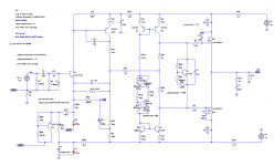
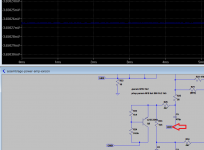
C9 is connected between the negative rail and GND, I confirmed with LT SPice and the (+) plus leg should go to GND right ?
As for C5, in LT spice the node between R25 (56ohm) and R26 (4k7) is always negative ... why is it wrongly placed ?
As for C5, in LT spice the node between R25 (56ohm) and R26 (4k7) is always negative ... why is it wrongly placed ?
After many tries probing the nodes I keep having the same measurements.... Am I doing something wrong ?
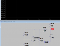
As GNDI is separated from GND by the 10ohm R52, I get a reading of -3.65mV there.... anyway this makes this node more positive than the previous one (-860mV)... so I believe I should connect the (+) leg of the cap to GNDI.... unless I am terribly wrong.
Attachments
- Home
- Amplifiers
- Solid State
- Assemblage Power Amp