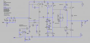
I believe I finally found a schematic that might work.
I am planning to use 0.2ohm emitter résistors on the output.
I am using 40ohm collector load résistors on the drivers.
No base stoppers because I am using single output devices MJL1302 and MJL3281 (very good SOA).
Driver's emitters go directly to the output.
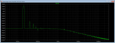
Idling voltage in the driver's bases is +-641mV (look at the wingspread).
The output circuit is a typical CFP.
I am planning to use 0.2ohm emitter résistors on the output.
I am using 40ohm collector load résistors on the drivers.
No base stoppers because I am using single output devices MJL1302 and MJL3281 (very good SOA).
Driver's emitters go directly to the output.
Idling voltage in the driver's bases is +-641mV (look at the wingspread).
The output circuit is a typical CFP.
Attachments

I believe I finally found a schematic that might work.
I am planning to use 0.2ohm emitter résistors on the output.
I am using 40ohm collector load résistors on the drivers.
No base stoppers because I am using single output devices MJL1302 and MJL3281 (very good SOA).
Driver's emitters go directly to the output.
Idling voltage in the driver's bases is +-641mV (look at the wingspread).
The output circuit is a typical CFP.
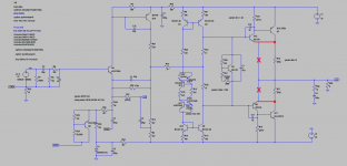
Hi RC, just one suggestion. CFP will work better if arranged this way.
Cheers,
Valery
Attachments
I believe I finally found a schematic that might work.
I am planning to use 0.2ohm emitter résistors on the output.
I am using 40ohm collector load résistors on the drivers.
No base stoppers because I am using single output devices MJL1302 and MJL3281 (very good SOA).
Driver's emitters go directly to the output.
Idling voltage in the driver's bases is +-641mV (look at the wingspread).
The output circuit is a typical CFP.
I would sleep better if you gave q12 and q6 a small emitter resistor (for thermal stability at the least).
Hi RC, just one suggestion. CFP will work better if arranged this way.
Cheers,
Valery
And that is fine too (just missed you post)
And that is fine too (just missed you post)
Yes, I also want to sleep better 😛
Hi RC, just one suggestion. CFP will work better if arranged this way.
Cheers,
Valery
I experimented your way and got much better results tying the driver's emitters to gnd 🙂
I would sleep better if you gave q12 and q6 a small emitter resistor (for thermal stability at the least).
10 ohms ok ?
10 ohms ok ?
Lower I would say, 4.7 or even 2.2?
Use '.step param re list 4.7 3.9 3.3 2.7 2.2 1.8 1.5' and see what happens with the wingspread.
Would also sim with MJE2955T and MJE3055T because these are in TO220 case and have reasonable SOA.
(The MJL are difficult to get, expensive and uge)
Unfortunately do not have the models for the MJE....
(The MJL are difficult to get, expensive and uge)
Unfortunately do not have the models for the MJE....
I experimented your way and got much better results tying the driver's emitters to gnd 🙂
😀 Much better results if your plan is to make a smoke machine

If you want to make an amplifier is better to follow the wise advice from Valery.
But you can skip the Valery advice and call it TSAR AMPLIFIER 🙂
https://www.youtube.com/watch?v=noY-Sd0DZqM
Now serious, emitter resistors in the output stage makes cross-over distortion worst, but you have to use it for thermal compensation, like you have in #183 is not possible, you do not have a fast mechanism that prevent thermal runway of the output transistors, Q5 alone can not compensate fast enough the increase current of the output transistors as they get hot, and the destruction of the output stage is inevitable.
using emitter resistors prevent thermal runway because when output transistor Ic increases the voltage at the emitter resistor also increases and that makes the voltage between the base and emitter of the output transistor decrease, this mechanism prevent the thermal runway of the output transistors.
using emitter resistors prevent thermal runway because when output transistor Ic increases the voltage at the emitter resistor also increases and that makes the voltage between the base and emitter of the output transistor decrease, this mechanism prevent the thermal runway of the output transistors.
use lat-fets for the ouput, they balance themselves and one pair will be sufficient for the voltage here.
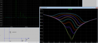
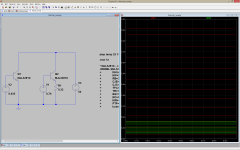
made this simple circuit for exemplify. changing the temperature from 25 to 150º makes the transistor without the emitter resistor to increase Ic from 150mA to 4A, the transistor with the emmiter resistor only increase Ic by 470mA in the temperature variation.
Attachments
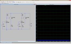
This circuit represents your TSAR output stage on the left and the Valery recommendation on the right, as you see changing the temperature from 25 to 150º will make the circuit from right increase 800mA and the TSAR will reach 37 Amperes , the SOA of the output transistor is violated with only 20º temperature increase. The driver transistor also fails.
Attachments
- Home
- Amplifiers
- Solid State
- Assemblage Power Amp