C5 and C9 are wrong, just probe over them in LT spice and see the DC vaoltages at the nodes.
My first reaction is, MiiB is right 🙂
As GNDI is separated from GND by the 10ohm R52, I get a reading of -3.65mV there.... anyway this makes this node more positive than the previous one (-860mV)... so I believe I should connect the (+) leg of the cap to GNDI.... unless I am terribly wrong.
Could it be that the -860mV changes with the source impedance, try to simulate I larger source impedance (100 Ohm or the about, just to see it's effect)
How do I simulate a different source impedance ?
Right-click the voltage source(V3) and set a value in the property-box 'Series Resistance', that's all 🙂 Also, doe not to expect to much of it, why?, have a good look at the input circuit, one thing I did not take into account 🙂
It is my opinion also 🙂
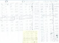
And if you want to know what I was doing the last 4 day's (about 10 hours a day), then see this table 🙂
Attachments
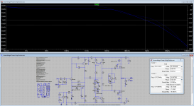
Here the GBW, Gain Margin and Phase Margin plots and figures for the Exicon amplifier version (a Tian-Probe was used). The amplifier should be stable ( 25gm > 20minimum, 74pm > 60minimum).
Attachments

Last edited:
Here the GBW, Gain Margin and Phase Margin plots and figures for the Exicon amplifier version (a Tian-Probe was used). The amplifier should be stable ( 25gm > 20minimum, 74pm > 60minimum).
THD is exemplary also. I believe this final version will prove to be something special.
Miib did his magic in the input stage, fine-tuning the VAS and choosing the correct values for the gate resistors in the output for the exicon.
Will fire it up soon 🙂
And if you want to know what I was doing the last 4 day's (about 10 hours a day), then see this table 🙂
Please explain 😱
( 25gm > 20minimum, 74pm > 60minimum).
what do these figures mean ?
what do these figures mean ?
(25gm > 20minimum, 74pm > 60minimum)
In the graph you can see that the gain margin (gm) of the Exicon amplifier is 25dB and that is more than the minimum needed of 20dB. Also, the phase margin is 74deg and that is more than the minimum value wanted of 60deg. That should make this amplifier stable.
In the graph you can see that the gain margin (gm) of the Exicon amplifier is 25dB and that is more than the minimum needed of 20dB. Also, the phase margin is 74deg and that is more than the minimum value wanted of 60deg. That should make this amplifier stable.
I would really like your input on those minimums..... Why do we need more than 20dB gain ?
Why is minimum phase margin set at 60° ?
PS: What is the super secret about your table ? I love tables, I am hooked on data treatment... I am a Certified Six Sigma Expert you know 🙂
Hello Miib
I would like to use some buffer caps on the rails near the mosfets drains. I see you placed there some small 1uF caps.... Can or should I not use bigger caps there ?
I am planning to place fuses on the rails also (I believe the mosfets can last longer than the fuses if anything goes wrong "a accidental output short for instance"), but should I be worried about the buffer caps ? Can I put the fuses before those caps ?
Hello Miib
I would like to use some buffer caps on the rails near the mosfets drains. I see you placed there some small 1uF caps.... Can or should I not use bigger caps there ?
I am planning to place fuses on the rails also (I believe the mosfets can last longer than the fuses if anything goes wrong "a accidental output short for instance"), but should I be worried about the buffer caps ? Can I put the fuses before those caps ?
Hello Miib
Hope you can guide me here... allready have the first board ready... just waiting for your input.
The small capacitors are there to aid stability rf decoupling sometimes lat fets are troublesome an need a hammer, the gate stopper is vital and if problems then a cap direct between the legs 22pf gate-drain, Here you should be out of trouble as the phase margin is good
Sorry for the delay, I have been a few days on holiday 🙂
First of all, to answer the question: 'Why do we need phase and gain margin', this is (IMHO) due to the fact that the load is part of the circuit. Loads come in different sizes and shapes, loads may be highly capacitive and/or inductive, the load then moves the margins, maybe even to the point where the margins go to zero, when that happens the amplifier will oscillate and most probably self destruct. This is why (with no (or a simple) load attached) you need some margin.
The figures 20dB and 60deg where (mis?)quoted from Bob Cordell his book 'Audio Power Amplifiers' (I thought 🙂) but I just checked the book and I can not find these numbers... The numbers that I can find (page 91) are, an absolute minimum of 6dB for gain margin and an absolute minimum of 45deg for phase margin. Now if you can tell me where I found the 20/60 numbers, I'm sure I got them somewhere.
The short answer, I can not find the long answer 🙁
These tables are, left to right, 4 columns for Cx, 4 columns for Cy, 4 for Cz and 4 for Rx (on the yellow attachment). These are the 4 components used to compensate my amplifier. The 4 columns are, 1st component value, 2nd gain margin, 3rd phase margin and last -3db gain bandwidth for the amplifier.
I would really like your input on those minimums..... Why do we need more than 20dB gain ?
First of all, to answer the question: 'Why do we need phase and gain margin', this is (IMHO) due to the fact that the load is part of the circuit. Loads come in different sizes and shapes, loads may be highly capacitive and/or inductive, the load then moves the margins, maybe even to the point where the margins go to zero, when that happens the amplifier will oscillate and most probably self destruct. This is why (with no (or a simple) load attached) you need some margin.
The figures 20dB and 60deg where (mis?)quoted from Bob Cordell his book 'Audio Power Amplifiers' (I thought 🙂) but I just checked the book and I can not find these numbers... The numbers that I can find (page 91) are, an absolute minimum of 6dB for gain margin and an absolute minimum of 45deg for phase margin. Now if you can tell me where I found the 20/60 numbers, I'm sure I got them somewhere.
Why is minimum ...
The short answer, I can not find the long answer 🙁
PS: What is the super secret about your table ? I love tables, I am hooked on data treatment... I am a Certified Six Sigma Expert you know 🙂
These tables are, left to right, 4 columns for Cx, 4 columns for Cy, 4 for Cz and 4 for Rx (on the yellow attachment). These are the 4 components used to compensate my amplifier. The 4 columns are, 1st component value, 2nd gain margin, 3rd phase margin and last -3db gain bandwidth for the amplifier.
From Douglass Self his book
... Solidstate audio power amplifiers are not expected to show
frequency response peaking or overshoot, and so
a phase margin of much less than 90
is not normally
acceptable. ...
- Home
- Amplifiers
- Solid State
- Assemblage Power Amp