I wonder whether SMD film capacitors indeed have substantially more inductance than similarly-sized SMD ceramic capacitors. I would expect SMD film capacitors to have a stacked construction, similar to multilayer ceramic SMD capacitors. Of course other disadvantages of SMD film capacitors are that they are relatively expensive and that some have a dielectric that easily melts during soldering. Any through-hole capacitor will have substantially more inductance than an SMD capacitor because of its leads.
No, it is a current source that drives a current through a high impedance resistor.Updated unfiltered voltage reference noise list, extended with the LTC6655:
LT3042 (unknown, presumably bandgap): 6 nA from 10 Hz to 100 kHz at 100 uA, so 189.7E-9 Iref/sqrt(Hz)
The current is very precise; together with 0.5% metal film resistors the result is
often exactly on the spot with 4.5 digit DVMs. The high impedance level makes it
easy to filter the noise away with a cheap capacitor. The output driver is exactly *1,
so the noise is not amplified.
The problem of band gaps is that the original effect is a quite small voltage that
must be amplified. That then includes their noise.
At least for a band gap. it invades buried Zener territory.The LTC6655's white noise is pretty low and it has a very low 1/f corner frequency, well below 10 Hz.

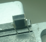
I have cut one open, if I remember correctly, made by WIMA.I wonder whether SMD film capacitors indeed have substantially more inductance than similarly-sized SMD ceramic capacitors. I would expect SMD film capacitors to have a stacked construction, similar to multilayer ceramic SMD capacitors. Of course other disadvantages of SMD film capacitors are that they are relatively expensive and that some have a dielectric that easily melts during soldering. Any through-hole capacitor will have substantially more inductance than an SMD capacitor because of its leads.
That was like a normal standing foil capacitor with the wires
bent upwards on the thin side again with a clip welded to each side.
Not too impressive. PE probably does not withstand the temperature
needed for direct face metallisation and board soldering without
the wire.
Non-PE may be better.
The usual way to make a DC current source on a chip is a bandgap reference followed by a transconductance amplifier (I mean a negative-feedback voltage-to-current converter, not an open-loop thingy such as an OTA). Hence my guess that the LT3042 uses a bandgap reference. If that guess is correct, it must have an accurate resistor on chip for the feedback. That means it is either made in a fancy process with accurate resistors, or uses trimming. In either case, the temperature dependence of the resistor must be quite reproducible (not necessarily close to zero, as you can correct for it by tweaking the bandgap).
You can stack instead of amplify PTAT voltages, that's the way the bandgap from the 1960's Electronics Letters article works. That's much less noisy.
You can stack instead of amplify PTAT voltages, that's the way the bandgap from the 1960's Electronics Letters article works. That's much less noisy.
Did you ever try the LT3042 datasheet circuit with LTC6655 filtered driving the SET pin? I'm sure it's not as good as what you've shown, but fewer components.You actually get quite far with filtering a precision reference, even a noisy band gap such as a LT6655. For a band gap ref , the LT6655 is actually quite good, but still far away from LT3042 etc.
This here is a quick & dirty test because I might have needed a ref for LT2500-32 ADC and had some free space on a board that had to be done SUBITO.
It is measured laying open on the lab table, and fed from a channel of a R&S NGT20 power supply. Therefore there are lots of 50Hz harmonics. I was only interested into the noise. 0 dB is 1nV/rtHz, about the input noise of an AD797 or LT1028.
I'm really thankfull for sharing your measurements with us.These ones should be shared on facebook honestly as there's so much disinformation about these professional solutions promoted by way too many guys that have no clue what they are talking about!You actually get quite far with filtering a precision reference, even a noisy band gap such as a LT6655. For a band gap ref , the LT6655 is actually quite good, but still far away from LT3042 etc.
This here is a quick & dirty test because I might have needed a ref for LT2500-32 ADC and had some free space on a board that had to be done SUBITO.
It is measured laying open on the lab table, and fed from a channel of a R&S NGT20 power supply. Therefore there are lots of 50Hz harmonics. I was only interested into the noise. 0 dB is 1nV/rtHz, about the input noise of an AD797 or LT1028.
@Bonsai,
Perhaps an unlikely result according to certain theoretical modeling, but quite noticeable in actual listening tests. If you tried the experiment I think you would say its so obvious that no DBT is needed.
As far as DBT goes, we do it frequently enough to stay calibrated. Even if we did DBT for an AVCC cap, the response from some in the forum would be to claim its an impossible result. The only way people will consider changing their minds is if they hear the difference for themselves. Just human nature again.
I'm not an expert in piano play... yet it's obvious he's damn fast even if he wouldn't hold a Guiness world record on that.I won't risk more off topic yet i would have liked more people watch him.He looks slightly bored, I think he sprinkles in a lot of other stuff just because there's not enough notes.
Am I the only one being annoyed at the loose flooring he's stepping on that he seems completely oblivious to?
Why would he dare to do something that would work against the audio business that he shills for?You would need to do a double blind test
What is this experiment that you are referring to?If you tried the experiment I think you would say its so obvious that no DBT is needed.
So you didn't do DBT for AVCC cap so far. Got it.Even if we did DBT for an AVCC cap, the response from some in the forum would be to claim its an impossible result.
Mark, you are claiming to hear a decoupling cap on the AVCC, that I am saying, if selected correctly, will result in a capacitance change of a few pF given the already very low noise (read: change in voltage) on the AVCC input. The only difference might be the MLCC impedance will be lower.
What else could change the sound in a way that you could hear a difference when switching between two circuits that are exactly the same save one uses a class II dielectric and the other something else?
What else could change the sound in a way that you could hear a difference when switching between two circuits that are exactly the same save one uses a class II dielectric and the other something else?
His listening position. 💡What else could change the sound in a way that you could hear a difference when switching between two circuits that are exactly the same save one uses a class II dielectric and the other something else?
Bonsai, I know some people will go nuts if I say this, but the fact is just a change from polypropylene to polystyrene is audible (although much more subtle). X7R sounds very bad in comparison to either of those. DA is a factor. We know it can be modeled as an RC ladder network. My not seem like much in the frequency domain, nor for steady state sine wave measurements. In the time domain DA time-smears the sound of LF transients (and perhaps the sound of higher frequency ones). You been engineering long enough to know about 'linear wave shaping?' Well that's what it is.
X7R is characterized with graphs of capacitance verses voltage if you are lucky enough to find the graphs. Possible DA, ESR, ESL changes tend to be completely ignored. Whatever is changing, and its likely more than one thing, the effect is audible if other system components are held unchanged.
EDIT: Speaking of a few pf, you ever used a gimmick cap for RF? Well, dacs run at RF frequencies. KSTR says impedance can matter at half the clock frequency for the reference voltage. It can change measured distortion. If distortion is changing dynamically the brain is more likely to notice it, nothing new there.
Last edited:
More unsubstantiated claims. 🙄but the fact is just a change from polypropylene to polystyrene is audible (although much more subtle).
.
.
Whatever is changing, and its likely more than one thing, the effect is audible if other system components are held unchanged.
Someone claimed that lifting speaker cables off of the floor with cable lifters resulted in audible improvement.
That's a similar one. You can see the solder clips. I did solder wires to itI have cut one open, if I remember correctly, made by WIMA.
That was like a normal standing foil capacitor with the wires
bent upwards on the thin side again with a clip welded to each side.
to put it on the bridge. 470.1 nF @ 1KHz.
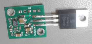
@ chris719 : no, I did not try this. The follower of the 3042 is quite week;
I could use an op amp just as well with less solder problems.
What I'd really want is a lt3042 for grown up men. Say TO-220-5
even when PowerGood is missing. The pic to the right is the circuit with
the npn from the data sheet. Practically the same performance as the
barefoot chip.
Attachments
Last edited:
Mark, the capacitor is used for DC decoupling- not AC signal coupling. Most here would never use a class II dielectric for the latter function. Film and electrolytic caps are severely limited at HF because of ESL/ESR - the very things you say X7R are bad at.
Nevertheless, the only test of this is a well executed DBT - since measurements of any kind are unlikely to show anything of significance either way.
Nevertheless, the only test of this is a well executed DBT - since measurements of any kind are unlikely to show anything of significance either way.
The life of Brian: HE JUST SAID JEHOVA!!!!1!1eleven!!Nevertheless, the only test of this is a well executed DBT - since measurements of any kind are unlikely to show anything of significance either way.
Oh, in #515 s/week/weak/
Last edited:
The pic to the right is the circuit with the npn from the data sheet.
Practically the same performance as the barefoot chip.
But no longer LDO ?
Patrick
Cool, you still know what LDO stands for! Many engineers seem to think it's synonymous with series regulator.
6.35Vin for 5.0V out @ 3 Ohm load minimum. That's what it took to feed my crystal oven until it is hot.But no longer LDO ?
Patrick
Probably I had more voltage for making the noise measurements.
BTW the 50 Hz harmonics did not stop suddenly @ 1 KHz, they are rendered as a higher noise level
because my software composed the picture from 7 FFTs, one for each decade. The 89441A uses
successively more bandwidth for higher decades, so it cannot tell the 50 Hz spaced lines apart @ > 1KHz.
I have changed that to octaves in the meantime. That gives more fine-grained results. A sweep takes
3.5 minutes now.
The proper scaling of the harmonics is a problem by itself. When the harmonic falls completely into one
frequency bin, it must not be corrected when computing noise density per rt Hz. But in the noise case
I must correct for the bigger BW per higher decade. Currently I do not make the distinction and handle
everything as noise. I could not find an algorithm to tell them apart.
Last edited:
- Home
- Amplifiers
- Power Supplies
- Are you really fine with IC voltage regulators ?