View attachment 1026657
Murata 22 uF 16 V 1206 X7R
View attachment 1026658
Murata 22 uF 16 V 1206 X5R
Both are pretty awful to me, even though the X5R capacitor is indeed worse than the X7R in this example. The working voltage and manufacturer also make a big difference, most of Murata's class-II capacitors are even worse than those of their competitors. You typically have to search the websites for characteristic curves to find data like these, the datasheets barely contain any useful information.
The MLCC’s offer low ESR and low ESL that you can’t get from film or electrolytics because of their construction. So if the capacitance varies by a factor of 80% it is really not an issue if the prime thing you are looking for is a reduction in supply impedance at the point of regulation by virtue of low ESL/ESR. Just oversize appropriately.

Yep. Choose the largest value in the package that has the mounted inductance you are requiring. If not low enough, add more in parallel. Programs like SiWave can show you how your design really works but is overkill for most cases.The MLCC’s offer low ESR and low ESL that you can’t get from film or electrolytics because of their construction. So if the capacitance varies by a factor of 80% it is really not an issue if the prime thing you are looking for is a reduction in supply impedance at the point of regulation by virtue of low ESL/ESR. Just oversize appropriately.
Bonsai and bohrok2610, the point I'm trying to make, but clearly not successfully, is simply that you need to take some safety margin if the capacitance matters.
Suppose you have a 10 uF +/- 10 % X5R capacitor. You then know exactly in what range its value will be over its -55 to +85 degrees Celsius temperature range at 0 V DC under the measuring conditions specified by the manufacturer: initial tolerance +/- 10 % and variation over temperature at most +/- 15 %, so it has to be between 0.9 * 0.85 and 1.1 * 1.15 times the nominal value, 7.65 uF to 12.65 uF. So far, so good.
Now suppose you want to use it at a nonzero DC bias voltage and the manufacturer's curves show that it loses 50 % at the voltage you want to use. As only typical curves are provided, you can't be certain it will be between 3.825 uF and 6.325 uF, it could also be somewhat outside that range. How much "somewhat" is, is anybody's guess. If the circuit needs at least 3.8 uF to work, I wouldn't go for this capacitor type, if it needs 3.5 uF, I wouldn't trust it either. If anything between 2 uF and 10 uF works, there is very probably no problem.
A much smaller effect that comes on top of this is aging. The specified value usually applies 1000 hours after the last time the temperature of the capacitor exceeded its Curie temperature. For every factor of ten increase of that time, the capacitance drops by a few percent. If only typical values are given for aging, you again have to take some safety margin.
We know this Marcel, and we are saying the same thing, but thanks for making it explicit.
Only use Class II dielectric caps for DC decoupling and size accordingly taking into account all the specs.
Only use Class II dielectric caps for DC decoupling and size accordingly taking into account all the specs.
Marcel, I fully agree with you. I was mainly trying to correct the IMO invalid claim of Jean-Paul's regarding XR5 being substandard.
Agree you should listen but I have a problem when we try to explain differences in sound with hypothesis that don’t stand to to scrutiny.
Don't stand to scrutiny based on what unstated assumptions about human hearing? That humans can't ever hear below a noise floor? Something else?
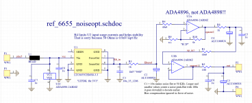
You actually get quite far with filtering a precision reference, even a noisy band gap such as a LT6655. For a band gap ref , the LT6655 is actually quite good, but still far away from LT3042 etc.Then why a precision refference and an op amp buffer with very high psrr and cmrr(if low impedance is needed) wouldn't be ideal for that?
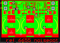
This here is a quick & dirty test because I might have needed a ref for LT2500-32 ADC and had some free space on a board that had to be done SUBITO.
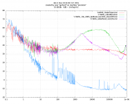
It is measured laying open on the lab table, and fed from a channel of a R&S NGT20 power supply. Therefore there are lots of 50Hz harmonics. I was only interested into the noise. 0 dB is 1nV/rtHz, about the input noise of an AD797 or LT1028.
Attachments
Which turned out to be valid. So again, X5R is inferior to X7R as it suffers more from capacitance loss with DC bias so one has to derate even more than usual. Therefor X7R is a better choice. There is almost no reason to choose X5R but choose X7R and upward!Marcel, I fully agree with you. I was mainly trying to correct the IMO invalid claim of Jean-Paul's regarding XR5 being substandard.
Both are crap when compared to C0G and film but we have to use them in some cases.
Last edited:
No it did not. X5R is only slightly inferior to X7R. Calling it substandard would make X7R substandard as well.Which turned out to be valid.
Slightly inferior = inferior. I would not call it slightly BTW. Why choose them?
Yes both are crap as already stated. It is like choosing which s**t stinks less. Capacitance loss with DC bias, Piezo-effect, some are hygroscopic, some develop cracks in them after some time with some brands, bodies of the caps becoming loose from the contacts. Things one will not experience as much with, for instance, molded TH film caps.
Their main qualities are low ESR, low ESL and of course key parameter low price.
Last edited:
X5R capacitors are often available in larger nominal values than X7R for the same case size. That's their one and only advantage over X7R, as far as I know.
Nobody has claimed anything else. But If I need a 4u7 0805 cap biased at 3.3V I have no issues using a X5R 50V cap.X5R capacitors are often available in larger nominal values than X7R for the same case size. That's their one and only advantage over X7R, as far as I know.
gerhard, why not bypass R1 and R4 (49R9) with suitable valued inductors, as is often done to phonostage inputs?
The 1000u store a lot of energy. When switching off Vcc, that would jeopardize the input clamping diodes of the op amps.
Updated unfiltered voltage reference noise list, extended with the LTC6655:
85A2 (glow discharge): 648.8 nV/sqrt(Hz) and 85 V, so 7.633E-9 Vref/sqrt(Hz)
National Semiconductor/Texas Instruments LM723 (Zener / avalanche diode), June 1999/April 2013 datasheet: 86 uV from 10 Hz to 10 kHz at 5 V output voltage, so 172.1E-9 Vref/sqrt(Hz)
LM317 (bandgap): 0.003 % of Vout from 10 Hz to 10 kHz, so 300.2E-9 Vref/sqrt(Hz)
uA7805 (bandgap): 40 uV from 10 Hz to 100 kHz at 5 V, so 25.3E-9 Vref/sqrt(Hz)
LT1236 (buried Zener reference): 2.2 uV from 10 Hz to 1 kHz at 5 V, so 13.98E-9 Vref/sqrt(Hz)
LT3081 (unknown, presumably bandgap): 5.7 nA from 10 Hz to 100 kHz at 50 uA, so 360.5E-9 Iref/sqrt(Hz)
LT3042 (unknown, presumably bandgap): 6 nA from 10 Hz to 100 kHz at 100 uA, so 189.7E-9 Iref/sqrt(Hz)
Diodes Incorporated TL431 (bandgap), June 2021 datasheet, not recommended for new designs: 230 nV/sqrt(Hz) at 2.495 V, so 92.18E-9 Vref/sqrt(Hz)
OnSemi TL431 (bandgap), August 2021 datasheet: 48 nV/sqrt(Hz) at 2.495 V, so 19.24E-9 Vref/sqrt(Hz)
Bandgap reference based on 1960's Electronics Letters article, schematic attached to https://www.diyaudio.com/community/threads/return-to-zero-shift-register-firdac.379406/#post-6881707 (bandgap): 29.784 nV/sqrt(Hz) at 4.96 V, so 6.005E-9 Vref/sqrt(Hz)
LTC6655: 17 nV/sqrt(Hz) at 1.25 V (Analog Devices datasheet page 7): 17 nV/sqrt(Hz) at 1.25 V, so 13.6E-9 Vref/sqrt(Hz)
The LTC6655's white noise is pretty low and it has a very low 1/f corner frequency, well below 10 Hz.
On it!Just hand me a drink while you are programming the DMX.
I'm having some rum in my coffee mug right now, planning a Mojito not too far into the future.
He looks slightly bored, I think he sprinkles in a lot of other stuff just because there's not enough notes.Maybe you'll like more a " degenerated" piano on a guitar fx by the officially fastest piano player in the world
Am I the only one being annoyed at the loose flooring he's stepping on that he seems completely oblivious to?
Okay, one more Mojito for you then.I'll have what he is having
But, they are not crap if used for the purpose for which they were intended! They are superb if you want to reduce supply impedance at HF. Last time I looked 1uF or 10 uF COG caps at 25V were not avaiablle in small sizes (I see values up to 0.47uF at 25V at $0.66 on Mouser). If you are using a fast opamp with high GBW it will require good local lo-z decoupling that probably won't be effective using an electrolytic or film cap.Which turned out to be valid. So again, X5R is inferior to X7R as it suffers more from capacitance loss with DC bias so one has to derate even more than usual. Therefor X7R is a better choice. There is almost no reason to choose X5R but choose X7R and upward!
Both are crap when compared to C0G and film but we have to use them in some cases.
This reminds me of an incident that happened over 30 yrs ago. A guy designed an isolation amplifier that used capacitors etched on opposite sides of a PCB to form the isolation barrier and presented it at the quarterly product release/technical forum. As he was showing it, one of the guys (who worked on RF stuff) started laughing and the presenter asked him what the problems was. 'You cant use etched caps like that because the values are all over the place - there's not enough control. It had to be explained to him (and the other guys) that it was the coupling mechanism that was critical, and in fact, the value could vary by a factor of 3 or 4 either way and it would still work fine because it was using the fast rise/fall times in a data stream to generate edge spikes that were being clocked into flipflop circuit to recover the data.
This is a good analogy for class II dielectric caps - you don't need highly accurate values or capacitance that is very stable over temp or voltage - you are looking for low ESL/ESR and small size so you can decouple locally and get the supply Z down. And, once in a circuit as a DC decoupler, the cap voltage is fixed - it might change by a few mV but that's it.
So I wouldn't call them crap - great little devices for what they are intended to do!
🙂
Don't stand to scrutiny based on what unstated assumptions about human hearing? That humans can't ever hear below a noise floor? Something else?
I think this exchange started off because you said MLCC (class II dielectric) caps could cause sound differences when used for decoupling a DAC AVCC because the value varied widely with voltage and temperature (correct me if I am wrong.)
I'm simply saying that once selected and sized appropriately given the information in the data sheet, its unlikely. You would need to do a double blind test, but I doubt you are going to get anything above the noise floor since as I explained, the change in capacitance with 100uV ripple (already 100x higher than you would have on the output of a LT3042) would be in the order of a few pF - i.e. negligible. If the DAC is showing that up, I'd venture there are other problems.
- Home
- Amplifiers
- Power Supplies
- Are you really fine with IC voltage regulators ?