Indeed, you just have to make sure that the voltage drop across D2 and D7 is high enough if there should be a current path into/out of the output of the op-amp.
yes, but in your case q2 an q4 have a full independent bias path to start q1,q3 and insure that ad823 is up and running...
Yes. No regulator should be without it ;-)
Jan
Interesting discussion. In the Superreg, the opamp is also supplied from the output voltage. There must be literally 100's of them been build, so far no complaints about startup.
Jan
Except you do not use diode at inverting and non inverting input of the op-amp. I think some op-amp can not start-up without those diode.
There are two ways to do it. Period.
Actually three, common emitter , common base or common collector, if we want or strive to be a little more inventive, which may be beyond , in this case the designated purpose - which is maybe why you referred to two ways... but nice to have a bit more inventiveness, methinks 🙂
they do the same as the old days CRD's in the other lower gain regulators...i don't know if they make CRD anymoreYes. No regulator should be without it ;-)
Jan
I do not understand your point that looks like a nasty comment against me, and completely out of contexteActually three, common emitter , common base or common collector, if we want or strive to be a little more inventive, which may be beyond , in this case the designated purpose - which is maybe why you referred to two ways... but nice to have a bit more inventiveness, methinks 🙂
To make it clear I was just saying that, in the context of serie regulators there are two ways to set the power transistor, common emitter or common collector.
Except you do not use diode at inverting and non inverting input of the op-amp. I think some op-amp can not start-up without those diode.
?? I have diodes there ...
Jan
?? I have diodes there ...
Jan
Of course, your schematic is good. 😀
I made it too using discrete op-amp.
Yes, exept they aren't there for start-up.?? I have diodes there ...
Jan
The base of the power trasistor is at a higher voltage then the Vcc of the opamp.You need a voltage shift to control the base from the opamp output.
Mona
I do not understand your point that looks like a nasty comment against me, and completely out of contexte
To make it clear I was just saying that, in the context of serie regulators there are two ways to set the power transistor, common emitter or common collector.
Not a nasty comment at all, simply to say the third can be very useful too.
Yes, exept they aren't there for start-up.
The base of the power trasistor is at a higher voltage then the Vcc of the opamp.You need a voltage shift to control the base from the opamp output.
Mona
Indeed. As clean and clear explained in #200.
Jan
Maybe i should bring back into discussion the fact that the first general regulator here :
https://www.diyaudio.com/forums/power-supplies/359652-fine-ic-voltage-regulators-18.html#post6336611
is the same emitter output type with Jan's regulator while the downstream ones are the higher gain,collector output ones
What i don't really understand i why they did this ,why they used two different regulators in series in the same equipment.
Is it because the higher gain ones have also a higher low frequency ripple rejection factor or because a collector output has a grater play under capacitive loading not loosing much of the amplifier's bandwidth ?
Normally in a regulator with a feedback opamp, the performance between an emitter or collector output doesn't differ much; it's more the implementation that counts.
But after all these years it is hard to try to 2nd guess the original designer. It may be the way they thought to get the best performance. You see it also on this forum, all kinds of designs, with varying success.
Often a part from one design is kludged onto a part of another design in an attempt to multiply the performance. Rarely works as expected.
Jan
#201 MvdG ! I missed that, same thing other words 🙂Indeed. As clean and clear explained in #200.
Mona
Normally in a regulator with a feedback opamp, the performance between an emitter or collector output doesn't differ much; it's more the implementation that counts.
Not really. The collector side is much higher impedance than the emitter,
so you need a lot of feedback to make it look as a low impedance generator.
That makes it dangerous stability-wise and that gave low drop regulators
their bad reputation as being bitchy.
Cheers, Gerhard
Not really. The collector side is much higher impedance than the emitter,
so you need a lot of feedback to make it look as a low impedance generator.
That makes it dangerous stability-wise and that gave low drop regulators
their bad reputation as being bitchy.
Cheers, Gerhard
Well said.
I was aware of this bitchy aspect. However I did not know, neither tried to know, why I had more trouble with the common emitter than with the common collector.
Now, I know the deep reason
Not really. The collector side is much higher impedance than the emitter,
so you need a lot of feedback to make it look as a low impedance generator.
That makes it dangerous stability-wise and that gave low drop regulators
their bad reputation as being bitchy.
Cheers, Gerhard
There is a very high feedback ratio in these regulators. I agree that in theory there should be a difference, but in actual implementations there is very little if any. The implementation is more important; a 1/2 inch wire between output and feedback point is enough to swamp any difference in topology.
Without remote sensing, there is always more wire than that between load point and feedback point, so that will dominate for output impedance and by extension for output current variation induced signal ripple.
Mains input ripple is un-measurable in both configs anyway due to the huge LF feedback factor.
Jan
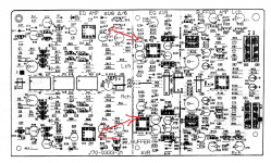
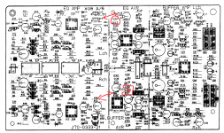
There isn't much physical distance between the regulators and their loads as they are on the same pcb. Looks like compact design...
Attachments
Last edited:
Because i'm working myself at reproducing the Nak's regulator, but making some small modifications for a higher output voltage, i was looking too see what other possibly did and i found this page:Interesting discussion. In the Superreg, the opamp is also supplied from the output voltage. There must be literally 100's of them been build, so far no complaints about startup.
Jan
Nakamichi Dragon – Rebuild & Improvements | LAB2104
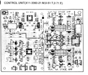
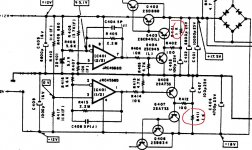
telling that the improvement they added to that regulator didn't match Jung's regulator, but what DIDN'T strike me was the fact that the modder wasn't looking at replacing the 1 kohm resistor biasing the final stage with anything better and i think that he had the correct feeling about that resistor, fearing replacing it with something that might cause instability, but didn't consider a take back to look at the full picture.
He mentioned about using very fast precise op-amps, as he didn't even see the original regulator using 3MHz FT final transistors driven by another two cascaded common emitter transistors biased by a 1kohm/100uf time constant network, they didn't see the enormous 6800uf output capacitor and certainly didn't look at the most crucial component that can add an improvement by being replaced with a current source as you or Kenwood did in your regulators.
What's even more hilarious is that the guy didn't realize that the Nak's biggest regulator used basicaly in every single high end cassete they produced is actually used as a Voltage Regulator more than a high performance ripple reducing stage as they have additional circuits doing that everywhere it is needed downstream next to the circuits in need while the regulator is 15...20 cm away from the most sensitive stages so its improvement would have been useless and at list this modder didn't understand that such a high standard company as Nakamichi would have been able to make the best regulator outhere if needed.
I think that there's so much misconception spread by the op-amp rollers that there will never be a consensus on how to really make things work out for the best.
Attachments
Last edited:
- Home
- Amplifiers
- Power Supplies
- Are you really fine with IC voltage regulators ?