Although entirely possible, i don't think they did it simply for fun unless i'm not able to understand the Japanese idea of fun 🙂
It's not really clear to me how they ensure start up for the common emitter case. With 0 output voltages and hence 0 op-amp supply voltages, the op-amps already have to supply the transistors with enough base current to make the whole thing start up. Maybe they use MOS op-amps so drain-bulk diodes will conduct current at start up?
For the common collector case, the current sources supply the base current. When the voltage of the Zener diodes between the op-amp and the transistor exceeds the minimum op-amp supply voltage plus one VBE, it should all work.
For the common collector case, the current sources supply the base current. When the voltage of the Zener diodes between the op-amp and the transistor exceeds the minimum op-amp supply voltage plus one VBE, it should all work.
I do not think electronics design is truly rational.Although entirely possible, i don't think they did it simply for fun unless i'm not able to understand the Japanese idea of fun 🙂
I have seen all sort of variants, many engineers who know their way is the best 😀.
A design choice, might very well, boil to, "they had one next door."
You even have designs based purely on trial and error. 🙂
I don't know...this was the last high end amp from Kenwood made by the same guys working for the Accuphase line... Overall it doesn't look like the average tinkering engineer's random design choice ...I'm clearly not at their level so i can't comment further.I did a lot of trial and error design in the last 2 decades, but i obviously don't work for Accuphase 🙂
Kenwood L-A1 on thevintageknob.org
Kenwood L-A1 on thevintageknob.org
Last edited:
A lot of my career as an engineer and consultant in hardware and software was actually fixing wacky designs.
You would not believe what I have seen.
My sarcastic remarks are generalities, nothing specific on accuphase design.
Well, out of topic, sorry.
How circuits start, is generally not designed beforehand, it is assumed it starts and usually it does.
I understand it is not granted as soon as there is a loop, in many cases it is not clear wether it will reach the operating point. When op amps are used you don't want to know much about what's going on inside. It is mostly unspecified, and yes some can lock up.
For instance, I designed Phase Lock Loops, not seeing how it will lock at power up. In most cases it did lock consistently and I had no need for adding some prepositioning trick.
Another issue is how it goes at power down, and here one might discover the need of protection diodes because of capacitor discharges. Another sneaky one is power down, with an immediate power up.
Some of the design is completed on the prototype. Wacky ones, mostly on the prototype.
I was proud to see my own designs work right away or with no more than minor fixes.
most of my time i was a tester and a fixer so i usually test and fix what engineers design with great care and immense knowledge 🙂
How circuits start, is generally not designed beforehand, it is assumed it starts and usually it does.
I understand it is not granted as soon as there is a loop, in many cases it is not clear wether it will reach the operating point. When op amps are used you don't want to know much about what's going on inside. It is mostly unspecified, and yes some can lock up.
In this case, the output voltages are controlled by an op-amp that only works when the output voltages are high enough. It seems clear to me that you have to think beforehand about start up with a circuit like that.
I agree.
What is the schematic of interest ? At what post number.
I understand, these work, old Japanese designs.
What is the schematic of interest ? At what post number.
I understand, these work, old Japanese designs.
I agree.
What is the schematic of interest ? At what post number.
I understand, these work, old Japanese designs.
Post #178.
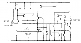
That also occurred to me, that's why I wondered whether they use CMOS op-amps (those almost always have drain-bulk diodes to the supplies). According to post #184 they don't, they use NJM2114 op-amps, which according to their datasheet have the attached internal schematic (although I have the impression that there are some polarities mixed up).
When the current has to flow into the output (positive regulator), the base-collector diode of the upper NPN current limiting transistor and the base-collector diode of the NPN output transistor provide a current path to the positive supply. So far, so good.
When the current has to flow out of the output (negative regulator), the collector to substrate diode of the NPN just below the output probably does the trick.
All in all, I think you are right.
Attachments
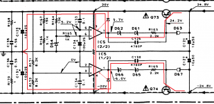
The way I see the start up.
At start IC5 is not powered, so it's output is 0V under some impedance from the output stage of IC5.
I guess this impedance is low enough to sink enough current through the zeners D62 D61 + 2.2K to bring the transistor into conduction. Then bingo, voltage appears at the 20V to give normal power to IC5
This asks for an inspection of what's inside IC5 at the output stage. A totem pole I presume. But more complex when under powered because it is an IC with a substrate that is actually a diode reverse biased when powered normally.
I guess the Japanese engineers measured the behavior of the output of that specific IC when underpowered.
May be a lengthy text equivalent to the previous posts.
Last edited:
Yes, indeed.
Is this topology a good idea from the Japanese engineers ?
I think it is because the bridge made of 3 resistors and a voltage reference is powered by a regulated voltage.
Is this topology a good idea from the Japanese engineers ?
I think it is because the bridge made of 3 resistors and a voltage reference is powered by a regulated voltage.
the output stage of njum 2114 is almost identical to ne5532(34) .2114 was advertised as a ne5532 improvement too...so we may have some options .At the same time why would you roll op-amps in a power supply especially when you have such a good op-amp as njm2114 there? i wouldn't replace njm2114 with anything in audio signal path if the circuit was designed for njm2114.This could lead to some nasty surprises for op-amp rollers...

- Home
- Amplifiers
- Power Supplies
- Are you really fine with IC voltage regulators ?