thanks again ! i wonder what could be the source of the high Hz noise ... if it comes from the mains maybe some kind of passive filtering before the mains transformer can take care of it. If instead it comes from diodes switching then is different. I see recommended another stage of regulation before the IC regulators with discretes resulting in a very positive synergy 🙂Cheap IC regulator usually ...
Maybe a similar effect can be obtained also with a little more complex discrete design
Another case when a spectrum analyzer could be very useful
You better read what you don't like...all you're writing for a while sounds like wishfull thinking...that won't be helpfull.
Last edited:
It's not the rectifier diodes by themselves, it's their turnoff delay (speaking of the common and ubiquitous 1N400x series) that gives a short current pulse causing the stray inductance of the transformer secondary to ring with stray capacitance, giving a large RF pulse that radiates and gets picked up by nearby circuitry. Due to the nature of it being transmitted, adding extra filtering to the power rails won't do much to fix it. It has to be fixed at the source where it's generated.thanks again ! i wonder what could be the source of the high Hz noise ... if it comes from the mains maybe some kind of passive filtering before the mains transformer can take care of it. If instead it comes from diodes switching then is different.
There are two common solutions, one is adding an RC snubber circuit across each rectifier and/or each secondary winding, the other is using modern rectifiers that switch off much faster when the current reverses. Both have been discussed here on diyaudio.
you mean this in the first place?
http://www.hagtech.com/pdf/snubber.pdf
Simple, no-math transformer snubber using Quasimodo test-jig
http://www.hagtech.com/pdf/snubber.pdf
Simple, no-math transformer snubber using Quasimodo test-jig
Last edited:
Well...may I translate the phrase in the photo into smth different?
If it's cheaper to adress the simptoms than the cause with simillar effects, i'll just do it, but almost all the manufacturers are doing a very different thing for more than 50 years already...instead of damping the low capacitance of the diode, they make it higher by adding capacitance in parallel to each diode lowering the oscilation frequency into a domain that won't couple easily, nor it will be difficult to be filtered.
There's also the case where tons of audiophile components from the 80's and 90's have no capacitor or damping at all, are using some low frequency diodes, but not 1n4007...Would those diodes have different behavior than 1n4007?
Attachments
Last edited:
According to Rod Elliot ESP site the Quasimodo transformer ringing bit is questionable.you mean this in the first place?
http://www.hagtech.com/pdf/snubber.pdf
Simple, no-math transformer snubber using Quasimodo test-jig
Snubbers For PSUs
The diode shootout in Linear Audio Volume 10, showed a strong correlation between reverse recovery time "Trr" and ringing amplitude. It showed an even stronger correlation between "Softness Ratio (Tb/Ta)" and ringing amplitude. But lots of today's diodes were introduced long long ago, and their datasheets were written long long ago. They were written so long ago that manufacturers did not measure or specify Softness Ratio.
So, if you find yourself far away from your copy of the LA article, with its table of diode specific part numbers and their ranking on the ringing amplitude test, it's convenient to pretend that smallness of ringing amplitude is perfectly correlated to diode recovery speed. It's not true but it probably is useful. Certainly that will prevent you from choosing the five worst diodes, for example.
So, if you find yourself far away from your copy of the LA article, with its table of diode specific part numbers and their ranking on the ringing amplitude test, it's convenient to pretend that smallness of ringing amplitude is perfectly correlated to diode recovery speed. It's not true but it probably is useful. Certainly that will prevent you from choosing the five worst diodes, for example.
post 83
thanks a lot. I will search advice for the best diodes around then
The filtering is more complex and the unit i have at hand is very packed with parts
I will ask about diodes and the best fixed voltage regulators available I guess that some brands are better than others and i could try swapping the original 24V regulators with something newer and better
Thanks again.
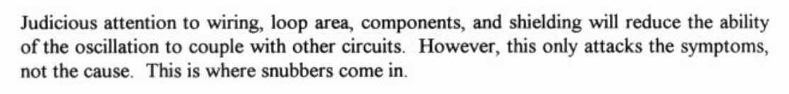
you might be true...I just looked at Nakamichi CA-7 and ca-50 high end preamp and their bridge is composed of fast rectifiers, but weird enough they have a supplementary 470pf capacitor across the output of the bridge...:
pdf.datasheetcatalog.com/datasheet/irf/10df6.pdf
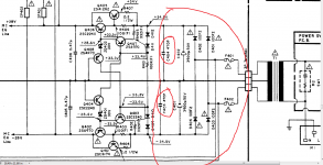
yet if i look at tecnics sl-p1000 cd player i see no high freq diode in their rectifier bridge, but i see the classical 22nf cap from the bridge input to ground...
1SR35-200 datasheet(1/2 Pages) EIC | SILICON RECTIFIER DIODES
pdf.datasheetcatalog.com/datasheet/irf/10df6.pdf
yet if i look at tecnics sl-p1000 cd player i see no high freq diode in their rectifier bridge, but i see the classical 22nf cap from the bridge input to ground...
1SR35-200 datasheet(1/2 Pages) EIC | SILICON RECTIFIER DIODES
Attachments
Last edited:
Well...may I translate the phrase in the photo into smth different?
If it's cheaper to adress the simptoms than the cause with simillar effects, i'll just do it, but almost all the manufacturers are doing a very different thing for more than 50 years already...instead of damping the low capacitance of the diode, they make it higher by adding capacitance in parallel to each diode lowering the oscilation frequency into a domain that won't couple easily, nor it will be difficult to be filtered.
In valve radios you usually find a capacitor in parallel with the valve rectifier, even though those have far less charge storage issues than semiconductor power diodes as far as I know (I'm no device physicist, so I could very well be wrong). Those capacitors are not meant as snubbers (circuits that help to keep a switching device alive) but as what is known in Dutch as a ratelcondensator, a rattling capacitor.
Via the interwinding capacitance of the mains transformer (or even directly when there is no mains transformer), one side of the diode is coupled to long mains wires that can act as an aerial. The other side is connected through a big electrolytic capacitor to the chassis of the radio, that can work as the return electrode for the aerial. Any RF signal that gets picked up gets modulated by the varying on resistance of the diode and retransmitted. AC shorting the diode for radio frequencies solves this.
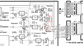
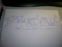
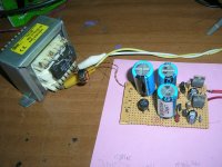
For those wanting a good bipolar 15V supply, this is what I use...
EDIT: I had the NTE numbers reversed.
This is the corrected diagram with the correct values.
Attachments
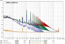
If you reverse the order of the stages also, i.e. regulator first,
C multiplier second, you may get 30 dB less noise.
Cheers, Gerhard
C multiplier second, you may get 30 dB less noise.
Cheers, Gerhard
The diode shootout in Linear Audio Volume 10, showed a strong correlation between reverse recovery time "Trr" and ringing amplitude. It showed an even stronger correlation between "Softness Ratio (Tb/Ta)" and ringing amplitude. But lots of today's diodes were introduced long long ago, and their datasheets were written long long ago. They were written so long ago that manufacturers did not measure or specify Softness Ratio.
So, if you find yourself far away from your copy of the LA article, with its table of diode specific part numbers and their ranking on the ringing amplitude test, it's convenient to pretend that smallness of ringing amplitude is perfectly correlated to diode recovery speed. It's not true but it probably is useful. Certainly that will prevent you from choosing the five worst diodes, for example.
It's a good article however a few things could be added WRT core quality and
magnetization level.
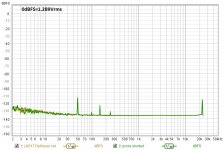
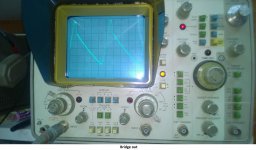
Years ago I was trying to attenuate a 100Hz buzz from a valve amp.
Observing the secondaries waveform showed *EXACTLY* the top waveform
on page 100 of your Linear Audio article.
I tried all sorts of soft recovery diodes and snubbers which worked to a small
degree. The real problem was core saturation tied with, presumably, P-S
leakage inductance. The mechanisms are complex. When there is any DC
component at the crest of the waveform as shown in that diag, there is a
very good chance the core will be driven into saturation further than it
already would be with a perfect sine wave. Coupled with any significant
leakage inductance and there is your energy release spike when the core is
coming out of saturation.
Changing the transformer solved the problem, the spike and buzz was largely
gone. The replacement was the same VA size and physical design, it must
have had a/ better quality iron or b/ ran it at a slightly lower magnetization level.
TCD
Zeners at <= 3V3 are wonderful. The onset of avalanching already at < 5V
destroys their noise behaviour.
That's what I read at various places and it also matches my own measurements of the noise of Zener/avalanche diodes, but I don't understand it anymore since I read a few articles about the noise of glow discharge voltage reference tubes.
According to J. F. Dix and K. B. Reed, "Cold cathode discharge tubes - Impedance and noise properties", Electronic Technology, vol. 39, no. 1, January 1962, pages 31...37, the noise voltage of a glow discharge reference tube is over a wide frequency range simply shot noise times an impedance equal to the ratio of the DC voltage across the tube divided by the DC current through it. Avalanche effects increase the noise current to much higher levels, but they reduce the impedance by the same factor, so the noise voltage remains the same.
Why doesn't the same apply to avalanching semiconductor diodes?
Those cold cathode discharge tubes are pretty, but being a plasma device they tend to be pretty noisy. Filtering out the noise with a cap doesn't always solve the problem either, especially if there are small signal tubes located close to them.
Still, they have good temperature stability and look super pretty.
Still, they have good temperature stability and look super pretty.
implementation issues
The wiring route from transformer's secondary to rectifying bridge to cap bank carries the HF spurae and spreads EMI pollution.
I keep the bridge very close to the transformer and if possible the caps as well.
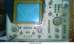
If not, I place a common mode choke in series to the distant caps (and twisted wiring).
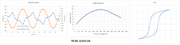
Regarding transformers, all those I have measured start to saturate at around 70% of their rated main's voltage.
It helps with voltage self stabilisation, but once saturation commences, magnetic flux leakage increases, making the transformer add to the EMI spread.
George
The wiring route from transformer's secondary to rectifying bridge to cap bank carries the HF spurae and spreads EMI pollution.
I keep the bridge very close to the transformer and if possible the caps as well.
If not, I place a common mode choke in series to the distant caps (and twisted wiring).
Regarding transformers, all those I have measured start to saturate at around 70% of their rated main's voltage.
It helps with voltage self stabilisation, but once saturation commences, magnetic flux leakage increases, making the transformer add to the EMI spread.
George
Attachments
Those cold cathode discharge tubes are pretty, but being a plasma device they tend to be pretty noisy. Filtering out the noise with a cap doesn't always solve the problem either, especially if there are small signal tubes located close to them.
When you look at the ratio of the noise and the DC voltage, they are not bad at all compared to the references used in solid-state voltage regulators:
85A2 (glow discharge): 648.8 nV/sqrt(Hz) and 85 V, so 7.633E-9 Vref/sqrt(Hz)
LM723 (Zener / avalanche diode): 86 uV from 10 Hz to 10 kHz at 5 V output voltage, so 172.1E-9 Vref/sqrt(Hz)
LM317 (bandgap): 0.003 % of Vout from 10 Hz to 10 kHz, so 300.2E-9 Vref/sqrt(Hz)
uA7805 (bandgap): 40 uV from 10 Hz to 100 kHz at 5 V, so 25.3E-9 Vref/sqrt(Hz)
LT1236 (buried Zener reference): 2.2 uV from 10 Hz to 1 kHz at 5 V, so 13.98E-9 Vref/sqrt(Hz)
Of course it's not entirely fair comparison since the 85A2 uses 467.5 mW in its recommended operating point, far more than the LT1236 or the references of the LM723, LM317 and uA7805.
Could be of interest for a high voltage regulator. You can use something like an LM317 with proper scaling, but that generally means a high ratio between the setting resistors and that high ratio also amplifies the reference noise. A high voltage low noise ref source would be a huge improvement.
Jan
Jan
LT431 is 120nV/sqrt(Hz) over1 KHz and 200nV/√ at 10 Hz with Vref = 2.5 VWhen you look at the ratio of the noise and the DC voltage, they are not bad at all compared to the references used in solid-state voltage regulators:
85A2 (glow discharge): 648.8 nV/sqrt(Hz) and 85 V, so 7.633E-9 Vref/sqrt(Hz)
LM723 (Zener / avalanche diode): 86 uV from 10 Hz to 10 kHz at 5 V output voltage, so 172.1E-9 Vref/sqrt(Hz)
LM317 (bandgap): 0.003 % of Vout from 10 Hz to 10 kHz, so 300.2E-9 Vref/sqrt(Hz)
uA7805 (bandgap): 40 uV from 10 Hz to 100 kHz at 5 V, so 25.3E-9 Vref/sqrt(Hz)
LT1236 (buried Zener reference): 2.2 uV from 10 Hz to 1 kHz at 5 V, so 13.98E-9 Vref/sqrt(Hz)
Is it correct to add:
LT431( bandgap ) 48.E-9 Vref/sqrt(Hz)
and 80. E-9
- Home
- Amplifiers
- Power Supplies
- Are you really fine with IC voltage regulators ?