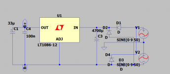
.With just using two bridge rectifiers, one for each secondary, you can make two identical, isolated, filter-and-regulator sections whose outputs can be put in series for symmetrical +/- DC outputs.
... is Mark Johnson’s VRDN something of this? (Asking just so I get an idea of what I’m reading/building. Electronics is to me as much a riddle as it is fun to be in „there“)
+1000 _ Because usually they do not know the PSRR of their circuit, ...
Hi ! i found very interesting that you mentioned listening tests comparing different power supply solutions
mine is just a feeling ... but i think that a very nice thing with discrete design is that the output cap can be made very big ... then a huge amount of ripple free voltage for the amplification circuit will be available, and moreover it could be placed also very very close to the circuit actually drawing the current 😉
With monolithic IC regulators this is not possible ... i understand that only some 10uF are allowed at their output 🙁
I also think that the higher the voltage the better. I have always in mind the photoflashes ... if i am not wrong they use the energy contained in a high voltage capacitor ? the discharge is lightning fast and very powerful
Attachments
Last edited:
actually there are countries where people can't by anything like that with 4 dollars.There are lots of things that cost 4 dollars in the US and 6 dollars in some parts of Europe.In Romania i have to pay an aditional 20...25 dollars for the transport of that lt3042 ...I just checked mouser and digikey and i need to pay abut 30 dollars in total for that lt3042.Then it's smd...which makes for the fact that i need to pay an additional 20 dollars for the minimum pcb quantity i can get from china and i also need to spend some hours to prototype that pcb too...All in all i pay 50 dollars for an application of that special IC...
If you buy stuff for >= €50 at Mouser or Digikey, the transport costs nothing
and the postman rings after 2 days usually. They are my primary source, too.
And JLCPCB has a proxy man now in Europe who gets one box with the daily
production, he does the customs, splits the jobs and sends them on with
intra-European mail, with new tracking number. Did cost €14.40 last time
for 10 boards 100*100mm.
And it does not take JLCPCB to deploy a simple 3042. Such a thing takes
2 hours from layout in the computer to soldering. It just takes a laser printer
with full toner, a sheet of transparent foil, a face tanner as UV source,
a glass plate and a corner of a presensitized board.
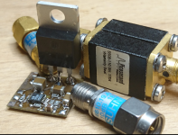
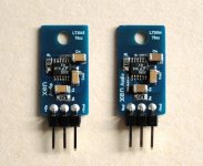
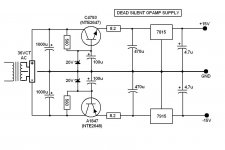
It's the circuit from the LT3042 data sheet with the extra pass transistor.
Yes, I would like a TO-220 version of that thing, too.
The coax stuff is only there to keep it from falling over for the photo.
Attachments
Last edited:
"If you buy stuff for >= €50 at Mouser or Digikey, the transport costs nothing"
Yes, indeed...i didn't buy anything from mouser or digikey here for a good number of years.I just chequed and indeed they do deliver for free for 50 euros woth of components.
Yes, indeed...i didn't buy anything from mouser or digikey here for a good number of years.I just chequed and indeed they do deliver for free for 50 euros woth of components.
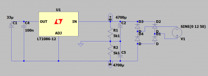
or you could keep it really simple...i just chose the first 3 terminal chip in the library...most op-amp circuits won't need more than that ground for bias.I've mentioned this before .... that it seems it easily pays for the four extra rectifiers.
Attachments
Last edited:
Hi ! i found very interesting that you mentioned listening tests comparing different power supply solutions
mine is just a feeling ... but i think that a very nice thing with discrete design is that the output cap can be made very big ... then a huge amount of ripple free voltage for the amplification circuit will be available, and moreover it could be placed also very very close to the circuit actually drawing the current 😉
With monolithic IC regulators this is not possible ... i understand that only some 10uF are allowed at their output 🙁
There are several errors in this reasoning.
Firstly, some monolithic regs have a minimum capacitance requirement for stability, but there's not a practical limit to the max.
But the elephant in the room is that with monolithic regs, the ripple suppression is so good that you don't need any large capacitor at the output - the reg is better than even a huge cap!
Jan
There are several errors in this reasoning...
Jan
Hi thanks for the very kind and valuable reply ... i have to answer without reporting your words as per instructions ...
I am sure you are right. But then i read of some listening tests that push the idea that regulators made out discretes are better received.
Let me elaborate a little my reasoning.
I have a preamp of a brand and it is the very entry level. The schematic is very similar to the one of the TOTL model. The biggest difference lies in the power supply ... even in a separate chassis for the TOTL. I do not know about its schematic ... but i am pretty sure that the TOTL model sounds better than mine. Maybe because adds another stage of regulation ... i am not sure about this.
But the whole point is that addressing the power supply and using a better design improves the sound. That is what i would like to do
I tend to think that differently from what i thought the preamp circuit is not the problem at all. Better ... the distortion is said to be very low ... the PSRR instead is not that wonderful and actually using a better power supply pays in terms of sound quality.
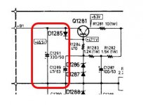
I haven't been looking through all the active threads lately, or I would have seen it and known what you're talking about. This thread gets me up to speed:... is Mark Johnson’s VRDN something of this? (Asking just so I get an idea of what I’m reading/building. Electronics is to me as much a riddle as it is fun to be in „there“)
VRDN: bipolar regulator PCB for line level ckts: ±11V to ±20V @ 1.5A with "De-Noiser"
And indeed I think I see a kitchen sink in the schematic. I see just about everything else. There are things that could be said about his heat sink calculations, but I'll refrain from saying them.
The first glance at the schematic indeed shows two bridges on the two secondaries, but that's about the only thing that's in common with what I was saying. Both regulators use the same "ground plane" connection, thus requiring the different LM317 and LM337 regulators. My idea is to have TWO ground planes (and two identical supplies, rather than the mirror-image schematic requiring different polarity regulator and transistor in each circuit). I was at first thinking have the "ground" connection at the output connections J5 and J6, but no, now I'm thinking not even that. Don't even have a ground connection between the two supplies, it's already at the board that these jacks connect to.
One of those Walt Jung articles discusses return currents and minimizing how far they go. Having separated positive and negative supplies helps to do that.
Hi thanks for the very kind and valuable reply ... i have to answer without reporting your words as per instructions ...
I am sure you are right. But then i read of some listening tests that push the idea that regulators made out discretes are better received.
Let me elaborate a little my reasoning.
I have a preamp of a brand and it is the very entry level. The schematic is very similar to the one of the TOTL model. The biggest difference lies in the power supply ... even in a separate chassis for the TOTL. I do not know about its schematic ... but i am pretty sure that the TOTL model sounds better than mine. Maybe because adds another stage of regulation ... i am not sure about this.
But the whole point is that addressing the power supply and using a better design improves the sound. That is what i would like to do
I tend to think that differently from what i thought the preamp circuit is not the problem at all. Better ... the distortion is said to be very low ... the PSRR instead is not that wonderful and actually using a better power supply pays in terms of sound quality.
Only thing I can say: if you add a large cap because you think it improves the sound, it will sound better.
Jan

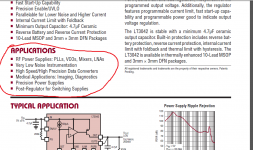
LT3045/3094
When we start discussing what sounds better, it becomes subjective and there is no right or wrong.
Everyone can choose what he believes, like religion.
Like Gerhard, I believe in measurements.
The LT3045/3094 is nothing but impressive, not only in terms of noise level, but also bandwidth.
I tried replicating its working principles with discrete components and got nowhere near.
For high current application such as power amps, I do not need tightly regulated supply.
So 500mA is more than enough fo rme.
You can also make it TO220 compatible.
The only thing is that it does not like a lot of heat.
But a 317/337 prereg will solve that.
And the caps recommended in the datasheet are way better than the normal Murata GRM's.
Cheers,
Patrick
.
Attachments
VRDN can be configured as two half-wave rectifiers, one for positive output and another for negative output; this allows the use of an AC wall wart with a single secondary. It also requires two opposite-polarity regulators (an LM317 and an LM337) since the common ground connection is foreordained and unchangeable. There's only one secondary.
On the other hand, when you abandon the feature to operate from a wall wart transformer with a single secondary, and instead require a within-chassis transformer having two independent secondaries, then you obtain the freedom to use two identical regulators, one for positive and the other for negative.
Personally, I'm fond of the idea of an AC wall wart. It keeps the AC mains out of the DIY chassis, which improves safety and reduces DIY chassis size (volume). The barrel jack connector cutout on the rear panel is smaller and far easier to drill, than a rectangular IEC mains inlet. Not surprisingly, both of the DIY headphone amps I exhibited & demonstrated at the 2019 Burning Amp Festival, used AC wall warts plus dual half-wave rectifiers. Attendees who listened to those HPAs ("Azul" and "Rojo"), liked what they heard.
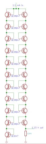
By the way, this is a relatively low-noise bandgap circuit that can be made of discrete dual transistors. It is similar to something that was published in the 1960's, but is almost never used. As drawn here it is relatively sensitive to variations in the input current; the transresistance from input current to output voltage is almost 286 ohm, so a 10 % variation of the input current changes the output voltage by about 31 mV or 2.5 %. A refinement could be to derive the 1.1 mA input current from the 1.23 V output voltage while ensuring the circuit doesn't get stuck at zero current and voltage.
Attachments
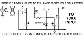
Unluckily, the 78xx may add more noise than the Vbe multiplier
has removed.
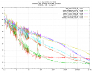
The measurements in #60 have been made with 10*NMH batteries
as the input voltage. These add no visible noise at all. All you see
comes from the regulator.
Those here are measurements of LEDs abused as voltage references.
The LEDs are fed from 14V through a 1 or 2 K wire resistor.
One trace has the diode replaced by 47 Ohms. All you see is the
thermal noise of the 47R, slightly below 0 dB = 1nV/rtHz which
would be the thermal noise of abt. 60 Ohm. Nothing from batteries.
Note the outstanding performance of the HLMP6000. I got that
from someone here, forgot who. I owe him a beer or two 🙂
Optically the HLMP6000 is quite a dim bulb.
My belly feeling is: the brighter a LED is, the more noise it does make.
has removed.
The measurements in #60 have been made with 10*NMH batteries
as the input voltage. These add no visible noise at all. All you see
comes from the regulator.
Those here are measurements of LEDs abused as voltage references.
The LEDs are fed from 14V through a 1 or 2 K wire resistor.
One trace has the diode replaced by 47 Ohms. All you see is the
thermal noise of the 47R, slightly below 0 dB = 1nV/rtHz which
would be the thermal noise of abt. 60 Ohm. Nothing from batteries.
Note the outstanding performance of the HLMP6000. I got that
from someone here, forgot who. I owe him a beer or two 🙂
Optically the HLMP6000 is quite a dim bulb.
My belly feeling is: the brighter a LED is, the more noise it does make.
Attachments
Last edited:
Hi thanks for the very kind and valuable reply ... i have to answer without reporting your words as per instructions ...
I am sure you are right. But then i read of some listening tests that push the idea that regulators made out discretes are better received.
Let me elaborate a little my reasoning.
Cheap IC regulator usually have good PSRR at low frequency. But we need good PSRR at high frequency because many audio circuit do not have good PSRR at high frequency.
In my country, it is difficult to get good IC regulator. So I design it. I modify Poogee regulator and Super regulator from Walt Jung with discrete op-amp. It is series and shunt regulator. Using zener or LED as voltage reference the result is better than cheap IC regulator in listening test. But I use shunt voltage reference from Walt Jung, also.
It is fun, the most important things 😀
Last edited:
"But we need good PSRR at high frequency because many audio circuit do not have good PSRR at high frequency."
Do we? Doesn't it depend on the circuit function they supply?
There are countless recording soundcards that are using analogue circuits with very poor psrr at high frequency supplied by switching supplies alone, lower noise ones, still smps...They have around 80...90 db PSRR at 1khz and much poorer at 10 khz,let alone the 100khz that we'll never hear, yet they are doing what they are supposed to do while artists and sound mastering engineers can't complain about weird noises or artifacts because they can't hear them at all...I have one of these and it sold amazingly well in the last 3 years being appreciated all over the world.Actually it was so well received that its price got higher than it was 3 years ago . Aren't we simply making artificially this problem to look bigger than it really is?
If a circuit supplied by a linear series regulator have poor psrr at 10khz and inaudible at 1khz...that's actually good enough because the mains harmonics around 10 khz are so weak that they can be filtered by a simple rc filter and most audio applications will have decoupling networks after the regulator..
Last edited:
Exactly. We need the good PSSR at low frequencies.
At high frequencies it is easy and cheap to filter.
At 1 MHz, 100n is a real short.
And circuits that require extra high PSSR are typical for
golden ear stuff. They usually have other problems, too.
At high frequencies it is easy and cheap to filter.
At 1 MHz, 100n is a real short.
And circuits that require extra high PSSR are typical for
golden ear stuff. They usually have other problems, too.
"And circuits that require extra high PSSR are typical for
golden ear stuff. They usually have other problems, too."
Or maybe we should read the datasheet of circuits like lt3042 exactly how they were written.
I can understand that they can be used for audio too, but....no mention of professional audio in the datasheet in the first place.LT3042 was simply ment for higher purpose ...
Attachments
With the additional transistor we can increase the current handling well, but voltage is limited to 20V ish.
Is there anything that does high voltages (30-40v) that comes close to LT 3042?
Is there anything that does high voltages (30-40v) that comes close to LT 3042?
- Home
- Amplifiers
- Power Supplies
- Are you really fine with IC voltage regulators ?