I have not forgoten dear Macd.... soon we gonna have a very good
image for Toner transference method (hot iron) and also to Photo Chemical process to prepare boards to etch.
Here you have a sample...a low quality one, to prove you we are working on that.
regards,
Carlos
image for Toner transference method (hot iron) and also to Photo Chemical process to prepare boards to etch.
Here you have a sample...a low quality one, to prove you we are working on that.
regards,
Carlos
Attachments
Senhor Carlos
thanks again for the information
I'm kinda a bass head but I would like to try a flat amplifier
If it is not troubling you
What is the revised pcb dimension for dx blame post #81?
Do you have the pcb drawing for your power supply?
Thanks and best regards
thanks again for the information
I'm kinda a bass head but I would like to try a flat amplifier
If it is not troubling you
What is the revised pcb dimension for dx blame post #81?
Do you have the pcb drawing for your power supply?
Thanks and best regards
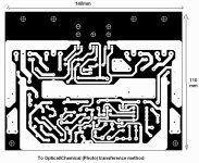
140 by 110 milimeters dear Dexter..... and soon you gonna have
this printed into the image.
Also the revised power supply layout will be published too.
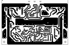
Here you have, attached, the final, revised (without dimensions we will include) pcboard layout to the power amplifier (all models uses the same board).
We will publish, another day, this same image having the dimensions on it..but will be the same image...for a while take note, the dimension is 140 by 110 milimeters...and you can check this watching the blue image..the amplifier image that have dimensions printed.
regards,
Carlos
this printed into the image.
Also the revised power supply layout will be published too.
Here you have, attached, the final, revised (without dimensions we will include) pcboard layout to the power amplifier (all models uses the same board).
We will publish, another day, this same image having the dimensions on it..but will be the same image...for a while take note, the dimension is 140 by 110 milimeters...and you can check this watching the blue image..the amplifier image that have dimensions printed.
regards,
Carlos
Attachments
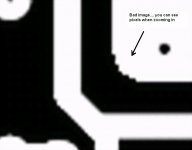
Here you can see the image to photo transference
This image will be improved and a PDF will be offered soon...so... wait a little bit..hold on for one more day.
This method, to the ones does not know:
First a transparency sheet of papper, used to image projection is prepared in high resolution..the image is almost entirelly black and only the copper tracks appear as transparent lines.
The virgin board... fiberglass having that copper sheet applied to one side, has ist's copper side covered (painted with brush) using a photo sensitive material that changes it's colour (turns darker) when receive light in high intensity...then, the dried material applied receive the transparent sheet directly over, or layed down over the copper side previously coated with photo sensitive material...then a strong ligth is applied.... a 500 watts bulb apply ligth to the set.
After that the board is ready...i really do not know if needs to be washed..but i know the copper tracks appear into the copper face..and these lines cannot be corroded, cannot be etched by the liquid we use to produce boards...so... parts that previously have not received ligth will be removed from the fiberglass board...and parts previously covered using the photo chemical layer will appear, after chemical corrosion, alike copper tracks.
The internet (youtube) have several examples and tutorials about.
In my place it is more popular the hot iron toner transference... as laser printer images and also Xerox machines copies can be used to apply image to the board.... also you can see several examples in youtube movies...in several languages.
The image attached was published if you are in a hurry...better image will be provided soon..without the defects you can see in the also published image.
regards,
Carlos
Attachments
Last edited:
I do not know..but i know it is adjustable depending to change a resistance
Soon Mitchel will inform you.
regards,
Carlos
Soon Mitchel will inform you.
regards,
Carlos
Hi coolet.
The time delay to activate the detection circuit is dependent on the voltage fed to the detector and on the frequency fed to the detector and to a lesser extent how long each signal lasted for.
One would have to model the circuit operation for a range of frequencies and a range of voltages and a range of pulse lengths to find the variable time delay.
If the time delay did not suit, then you could change some of the RC filter values and then model for the modified circuit.
where you can see builder's pictures...looks alike because 100 brazilians have ordered kits..including parts... transformers, and now they are starting an enclosure group buy and finishing the heatsinks group buy...pictures are not so different, because boards and parts are almost the same (group buy)
Tests are published too..... the basic scope inspections and some audio torture will be shown in videos uploaded to Youtube...the links will be posted too.
Notice videos are uploaded too.... we are working fellows... to be offer you a safe amplifier, a tested one... a guaranteed one.... a reliable one ...an aproved by users one..... they will be tortured ...if smoke, will happens at my home and not at your home!
YouTube - Notice!, the Blame MKII and the Supercharged
YouTube - Supercharged, low power basic scope inspection
YouTube - Supercharged, 10khz square wave - 228 watts RMS
regards,
Carlos
Hi Carlos, what kind of multimeter is the one that you use in the video with the - outstanding - 10 kHz square wave?
regards
Konstantinos
My Multimeter is a generic one, common, normal, standard one
These multimeter uses the same chip..there are few variations about the chip you can find inside...they are almost standard to all multimeters..a dedicated chip to this function.
It is precise from 40 to 200 hertz when sinus wave is measured, then a rms output is displayed.... not so precise.
My scope has attenuation and correction of wave shape inside the enclosure, then a cable runs out from the cabinet to be soldered into the load (2 resistances of 7 ohms and 70 watts).
The scope was a gift from Dudainc, a forum friend that travelled from the States with the scope in his hands to make a gift to me...also one of my two multimeters that was small present from an electronic factory that gave him two multimeters, one he sent me.... the strange thing is this multimeter measuring square waves and also high frequencies (not precise this way) when it shouldn't measure such frequencies or wave shapes.
Now i have an external probe point with attenuator, a standard one..but not so good to use, as may melt while attached to power resistive loads while i produce torture high power testings..the 140 watts resistance turns too much hot when i apply 270 watts.
I hope i have understood your question..if not, then ask again.
regards,
Carlos
Father Carlos
Are you able to put some text on the PCB track schematic? This way people will know which is the right way around when etching their boards. Am I looking from the top component side, or bottom soldered side?
Yes I am making another Blame amp. Blame ES this time🙂 Thanks for your great effort in your pictures "Mitchel".
Regards
Niss_man
I know the questions was not for me dear Simon
But Mitchel is busy these days...he is preparing a site to host Dx Blame informations...he wants another one, even considering we have, thanks lord, Greg Erskine site.
I would like to thank Greg Erskine once again, as he always have supported Dx amplifiers..since the very early begining the made boards, he tested, he cooperated and have opened these pages we use...also he have helped Nordic and other layout designers, about the Eagle operation:
http://users.tpg.com.au/users/gerskine/dxamp/
Mitchel is preparing another one because some brazilians are not able to read in english..they feel not confortable reading in other language than their own, when boards are Made in Brazil, and the designer is a brazilian too.
But for sure he will listen you dear Simon and the informations you want will be included if possible... please, make a more specific request, with some more details about what you need.
regards,
Carlos
Last edited:
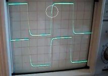
Clearly visible unstability on rising edge...outstanding - 10 kHz square wave?
Thank you dear Schiller
From time to time someone comes to sow discord... the one trying to do this, if not find fertile ground, go away as fast as arrived .. do not answer dear Schiller, please,... never mind.. .there are waveforms published in books that supports your evaluation.
Answers will only give good land to the seed grow.
It seems you follow the same book i use to follow dear Schiller.... well...maybe the book is wrong...but the unit is sounding awsome this way.
regards,
Carlos
Attachments
Last edited:
It appears that you are still strongly believing that you are infallible, dear Carlos. It is not better and safer (and cheaper) for users and builders to eliminate basic design errors? But if you want to remain in mistakes , it is Your decision. And I was talking about "stairs" in rising edge...
Here you have the power amplifier layout for toner transference method
I hope, this way, you will be able to produce your pcboards at home.
Also the speaker protector layout for toner transference method and the new supply (without rectification) layout for tone transference method.
Soon we gonna have a site to join all these pdfs together
regards,
Carlos
I hope, this way, you will be able to produce your pcboards at home.
Also the speaker protector layout for toner transference method and the new supply (without rectification) layout for tone transference method.
Soon we gonna have a site to join all these pdfs together
regards,
Carlos
Attachments
Clearly visible unstability on rising edge...
Amplifier or generator ? it appears in the video output mirrors the input how where u able to determine the amp from the generator signal ?
Sorry i do not see what you speak ..... 😕
- Status
- Not open for further replies.
- Home
- Amplifiers
- Solid State
- Are you ready to face strong emotions?.. Dx Blame MKII and the Supercharged release!