I agree that this might be good. but the following might be one better.I would think that a circular baffle with the driver mounted off center would be optimal
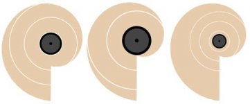
Comparisson of a circular baffle with off-centre driver, and a baffle with each vector from driver centre to baffle edge increasing linearly. (Requires SVG plugin)
How far off center do you need to be to be considered off center? Millimetres... inches...?
I would assume it is frequency dependent?
Cheers
Steve
I would assume it is frequency dependent?
Cheers
Steve
More than a few mm certainly. I guess you want to minimise the amount that falls off the baffle at any one time. In which case a circular baffle is not really that good because no matter where you place the driver, the baffle space is always symmetrical on either side of it. In which case, it may be that a rectangular baffle with careful driver positioning is better.
But I think the snail shape is better still.
But I think the snail shape is better still.
Mount the speaker on a stand as rigid as possible and put the baffle in front of it - without any effective mechanical contact.
Stixx, sorry for the delay in replying but I have been on a short break.
With regard to the above quote, you may find THIS of interest! The results confirm that this is a good way to go with OBs.

Vikash- Very astute observation regarding the circular vs. snail shape. The snail shape is quite popular these days used in other ways (B&W) . Maybe Stixx can come up with a great design based on it.
BUT, first we have to figure out how to change the snail to set it on the floor. For example if we placed the shortest radius on the floor, that would become the longest radius.
BUT then the driver is well below ear height.
BUT we can angle the driver back as bit, So that's what still needs thought. I would think that the driver needs to be, say 60 cm off the floor to avoid extreme tilting, and to keep it from interacting with the floor.
BUT closer to the floor would increase the bass?
BUT the angle needs to be adjustable to adjust for the listener being different distances from the speaker,
AND tilting back the driver and baffle more will roll off the upper mids, which tend to be exagerated with many full range drivers
Variac,
I've recently abandoned my attachment to boxes, and I'm keen to get started with open baffles. I can get hold of polycarbonate through some contacts, so I plan to do a design, perhaps based on my snail shape observation using maybe 25mm thick material 😉
Why does the shape need to be on the floor? I was thinking of suspending it at the right height using some sort of stand. No issue with tilting then either.
Will post some conceptual designs soon...
If anyone has any good resources to get started with open baffles (theory) then I would appreciate links...
Vikash -
The place to go for dipole theory is
http://www.linkwitzlab.com
Everything you want to know and more is there.
The baffle does not need to be on the floor, and probably would have smoother response if it did not. Most designs rest on the floor in order to reduce the effect dipole cancellation and extend the bass response.
I agree with your assessment of the inherent symmetry of the circular baffle and like your concept of the spiral shape. I wonder, however, what the effect would be of the discontinuity as you reach the end of the expansion and drop straight to the smallest radius. Could be a great place to mount a long ribbon tweeter...
Have you considered an oblong or egg shape. I think this would have great possiblities.
Determining the offset of the driver is a function of the baffle size and shape rather than a frequency. If you calculate the Fpeak response of a certain baffle size, you will get a series of peaks and nulls. Driver placement should be determined so that the different offsets create peaks and nulls that are complementary (opposite phase). This would result in the smoothest response.
Sjef -
I'm using the ESG as a supertweeter with a 4th order highpass at 9kHz, so it's hard to give a good assessment of the ribbon. I'm not satisfied with the response as is, but I only set it up as a temporary solution. I expected to be working on a new crossover design, but I've been busy this summer building a dipole subwoofer and filter to fill out the bottom end. The sub has turned into a major construction project, but I'm finally getting close to completing it.
Once the sub is up and running, I'll be tuning the system as a whole.
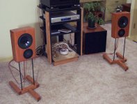
I dont know if I posted in this thread yet, but here are my open baffle dipoles. The sub is an open baffle dipole, with two 12's in a w-frame as outlined on LinkwitzLab. The Mains use full dipole equalization and are crossed to the sub at 90Hz.
-Paul Hilgeman
-Paul Hilgeman
Attachments
Hi Erik,
The way I see it is that the descent starts at the point where the wave first starts dropping off the baffle, then gradually decreases until the wave length is larger than the outermost point on the baffle. The length before the wave begins to drop off should dictate at which frequency the drop begins (at least in my mind 😉 ). I wonder if I can use a baffle large enough and cross over to the sub at the point where the wave equals the baffle's longest length - with the aim of avoiding the wild peaks and troughs that would result after this point?
Another thing to take into account may be something that Kuei mentioned about wavelaunch, which may dictate the minimum point from driver to baffle edge.
RE. Linkwitz site. I coudn't find the intro theory I was looking for last time I looked. Will have another sniff around.
Not sure what you mean by droping to the smallest radius.I agree with your assessment of the inherent symmetry of the circular baffle and like your concept of the spiral shape. I wonder, however, what the effect would be of the discontinuity as you reach the end of the expansion and drop straight to the smallest radius. Could be a great place to mount a long ribbon tweeter...
The way I see it is that the descent starts at the point where the wave first starts dropping off the baffle, then gradually decreases until the wave length is larger than the outermost point on the baffle. The length before the wave begins to drop off should dictate at which frequency the drop begins (at least in my mind 😉 ). I wonder if I can use a baffle large enough and cross over to the sub at the point where the wave equals the baffle's longest length - with the aim of avoiding the wild peaks and troughs that would result after this point?
Another thing to take into account may be something that Kuei mentioned about wavelaunch, which may dictate the minimum point from driver to baffle edge.
RE. Linkwitz site. I coudn't find the intro theory I was looking for last time I looked. Will have another sniff around.
Let me try with pics...
I've changed two variables here which I think are directly related to the point where the drop begins (second image), and the rate at which the drop occurs and ends (third image).
I'll be the first to admit that I know very little about all this. So please tell me shut up if I'm chatting rubbish (and correct me).
Attachments
An oblong or egg shape would have the same symetrical issues as a circle I think. If there really are symetrical issues.
Yes the reason people have the baffles go to the floor is that you get a free lunch- the equivalent of a a very large baffle, which keeps the baffle overall from needing to be as big as it would otherwise (which would be very big I believe)
I was also trying to point out that tilting the driver so that it isn't on axis with can be a good thing- it rolls off the upper frequencies
which is something a lot of wide range drivers emphasize. Sometimes too tilted wil creat an uneven response however.
So my interest is how to best transition from the part on the floor which is a huge edge of the baffle, to any other side, which is much shorter.
Examples of stylish baffle design
I finally recovered a lost link to some very stylish baffle design proposals. They were not intended for OBs in the first place, but I believe they have high WAF.😉
http://www.tweakstore.com/index.html
Just follow the arrowhead buttons and have fun.
I finally recovered a lost link to some very stylish baffle design proposals. They were not intended for OBs in the first place, but I believe they have high WAF.😉
http://www.tweakstore.com/index.html
Just follow the arrowhead buttons and have fun.
quite lovely. I think the secret is to have the wings spring loaded with a pneumatic screen door closer. You have to manually extend them to start listening. When the amp is turned off, a relay latch unhooks and the wings slowly fold back and disappear!
excellant SAF 😎
No info on whether we can have gaps or not?
excellant SAF 😎
No info on whether we can have gaps or not?
Gap between speaker and baffle?
Variac wrote
I believe one has to bear in mind that Obs are velocity transducer in contrast to box constructions, which are pressure transducers.
Along the baffle of an OB the pressure waves of sound are travelling like water in a river bed. If there are some small holes in the riverbed, some water will escape, but the mass of the water will flow on. It much depends on the cross section ratio between leak and main flow.
What Erik was talking about is IMHO more like a leak in a pressurised water pipe (and that seems to me more like an analogy to a sealed box). Obviously in this case the water loss through the leak is more dependent on the water pressure than the pipes diameter.
So if we keep the gap between baffle and speaker to a minimum (just enough to avoid mechanical contact) there should be not much loss of audio energy.
Looking at it from practical experience:
I use the drivers of my OB alternately in a MLTQWP. Holding my hand over the pipe I can feel the impulses of moving air already at normal listening levels (seems to be a lot of pressure in there). But I could never feel anything comparable while holding my hand near to the speaker on the OB. 😉
Variac wrote
I don´t have scientific evidence on this. But here are my thoughts:No info on whether we can have gaps or not?
I believe one has to bear in mind that Obs are velocity transducer in contrast to box constructions, which are pressure transducers.
Along the baffle of an OB the pressure waves of sound are travelling like water in a river bed. If there are some small holes in the riverbed, some water will escape, but the mass of the water will flow on. It much depends on the cross section ratio between leak and main flow.
What Erik was talking about is IMHO more like a leak in a pressurised water pipe (and that seems to me more like an analogy to a sealed box). Obviously in this case the water loss through the leak is more dependent on the water pressure than the pipes diameter.
So if we keep the gap between baffle and speaker to a minimum (just enough to avoid mechanical contact) there should be not much loss of audio energy.
Looking at it from practical experience:
I use the drivers of my OB alternately in a MLTQWP. Holding my hand over the pipe I can feel the impulses of moving air already at normal listening levels (seems to be a lot of pressure in there). But I could never feel anything comparable while holding my hand near to the speaker on the OB. 😉
If your aesthetic sense calls for a circular baffle with a centrally mounted driver, just make the circle into a star (with as many points as you like), or something like a stylized sun. That should create a smooth, ripple-free spatial transition. The length of the points relative to the unbroken baffle would determine the width of the transition. You could also accomplish the same thing by drilling concentric rings of holes of increasing size.
These ideas would also work for square and rectangular baffles.
Bill
These ideas would also work for square and rectangular baffles.
Bill
Bill F. said:make the circle into a star (with as many points as you like), or something like a stylized sun.
Good idea... i used a similar concept for the diffraction killer pictured.
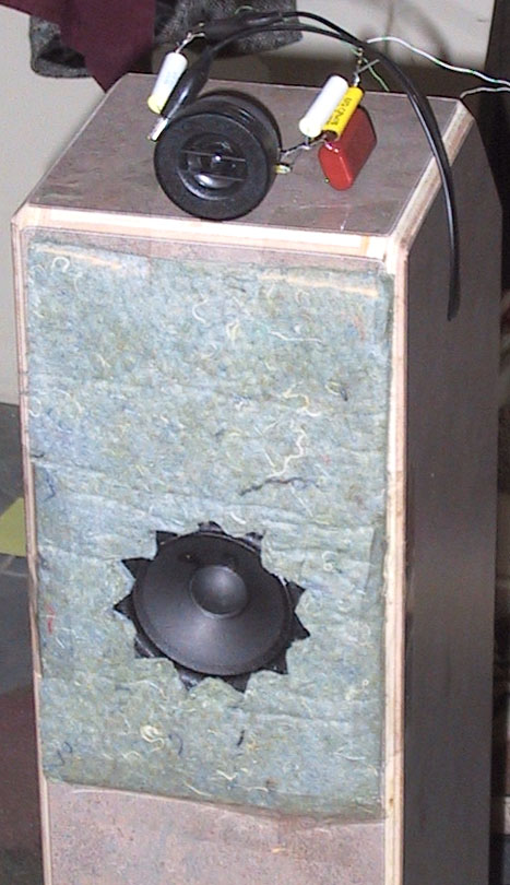
I like an odd number of points and on the felt-star i also beveled the edges of the cutout.
dave
Cool, Dave.
Functional is the ultimate aesthetic!
I have some pretty extreme ideas about using absorbtive materials for diffraction control, even extending into absorbtion of stray lobes/ pattern control. I call it "Acoustic Collimation." 🙂
Bill
Functional is the ultimate aesthetic!
I have some pretty extreme ideas about using absorbtive materials for diffraction control, even extending into absorbtion of stray lobes/ pattern control. I call it "Acoustic Collimation." 🙂
Bill
PaulHilgeman said:I dont know if I posted in this thread yet, but here are my open baffle dipoles.
Thanks for posting the pics. I like the match of the open baffle speakers and open baffle power amp.
Here's some cool baffle material. Irritating website design though.
If anyone finds out the cost please report.
http://www.e-panelite.com/
If anyone finds out the cost please report.
http://www.e-panelite.com/
- Status
- Not open for further replies.
- Home
- Loudspeakers
- Multi-Way
- Are you (open) baffled yet?