Neb, I'm using a modified version of your code base. Now playing with the IR (took ages for Mouser to send the receiver) so using an alternative.
Seems to be working apart from the fact there is no repeat on Vol+/-. Should that be working? TIA Gary
Take the latest from here:
https://drive.google.com/drive/folders/0B74euvw8ey5JOENmRXNYUEtySVE
I think at some point I left one of the params at wrong value:
//------- do not edit below this point ----------------------------------------------------//
#define TIME_IGNOREREMOTE_VOL 100 // Time in millisec after IR VOLUME before repeating
#define TIME_IGNOREREMOTE_CMD 100 // Time in millisec after IR command before repeating
#define TIME_SWITCHBOUNCE 250 // Time in millisec to debounce switch
#define TIME_IRBOUNCE 200 // Time in millisec to debounce IR button
#define TIME_DACSETTLE 500 // Time in millisec to wait for the DAC to stabilize after setting output
#define TIME_RELAYLATCH 0 // Time in millisec for latching I/O relay driver to stabilize (0 if using non-latching relays)
Thanks for the update but my remote won't volume repeat with that either.
Attached is my code butchery 😉 but I now have the remote Vol repeat working. And the whole thing seems quite responsive.
There are a few other changes too:
Attached is my code butchery 😉 but I now have the remote Vol repeat working. And the whole thing seems quite responsive.
There are a few other changes too:
- I'm using a hardware debounce on the encoder and it is a half-step encoder
- I have dropped the newPulsein code as that feature is already in current versions of IDE. There is a parameter to tune the timing around the remote
- I've dropped various code segments on to thier own tabs to help me in my understanding of it.
Attachments
Thanks for the update but my remote won't volume repeat with that either.
Attached is my code butchery 😉 but I now have the remote Vol repeat working. And the whole thing seems quite responsive.
There are a few other changes too:
Got some 16-bit I2C ADC today need to get my head around them. If that works out I will move on to DACs which I think will give the best improvements.
- I'm using a hardware debounce on the encoder and it is a half-step encoder
- I have dropped the newPulsein code as that feature is already in current versions of IDE. There is a parameter to tune the timing around the remote
- I've dropped various code segments on to thier own tabs to help me in my understanding of it.
Thanks. Tried your code, but repeat no worky for me. Encoder no worky either. You are probably using different hw.
It seems that new IDE 1.8.1 broke IR part of the code completely. IR does not work at all, even though it compiles without errors. Works fine when I revert to 1.6.9.
Neb,
I have a half step encoder but it is using a hardware debounce circuit. Comment out line 74; #define HALF_STEP for a single step encoder. And set lines 288 & 289 to
pinMode(PIN_ENC1, INPUT_PULLUP);
pinMode(PIN_ENC2, INPUT_PULLUP);
On the IR side I decided to drop the newpulsein code as its timeout feature has now been implemented in IDE for a while now. The timeout value can be tuned by adjusting the value on line 76; #define RemoteIRTune 20000.
If you use the newpulsein code I found I had to tune the value of the number after the * on line 1287 (your file); return clockCyclesToMicroseconds(width *
Neb,
I have a half step encoder but it is using a hardware debounce circuit. Comment out line 74; #define HALF_STEP for a single step encoder. And set lines 288 & 289 to
pinMode(PIN_ENC1, INPUT_PULLUP);
pinMode(PIN_ENC2, INPUT_PULLUP);
On the IR side I decided to drop the newpulsein code as its timeout feature has now been implemented in IDE for a while now. The timeout value can be tuned by adjusting the value on line 76; #define RemoteIRTune 20000.
If you use the newpulsein code I found I had to tune the value of the number after the * on line 1287 (your file); return clockCyclesToMicroseconds(width *
Tried, it does not make a difference. Repeat still does not work. Original code works fine though.
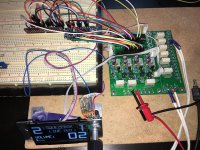
I'm using IDE 1.8.1 without the newpulsein and just pulsein and IR is fine and has Vol repeat working but as I say I had to play around with the timeout value.
I am using a different IR receiver though cos the correct one I ordered from mouser has still not be forfilled. I also choose to power the receiver from the 5V rail and not the 3.3V.
I am using a different IR receiver though cos the correct one I ordered from mouser has still not be forfilled. I also choose to power the receiver from the 5V rail and not the 3.3V.
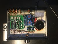
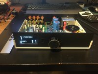
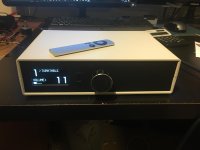
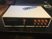
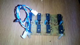
I need to get some real listening done so have now housed the boards. Nothing fancy just a basic build.
In the background I'm working on MK II, for want of a better description, it will use I2C ADC & DAC's to manage the LDRs. Hopefully this will give better accuracy and get rid of the mid point bump.
In the background I'm working on MK II, for want of a better description, it will use I2C ADC & DAC's to manage the LDRs. Hopefully this will give better accuracy and get rid of the mid point bump.
Attachments

Hello.
I'm having some problems with my LDR controller. I can't set the bias higher than 100kohm on my LSH and RSH LDRs (the shunt resistors). I wonder where I have made a mistake? I already checked most of resistor values but some are difficult to get to at this point of build. This is my second build with these devices and the first one was successful. Any help would be highly appreciated as I'm quite stuck now.
I have a headphone amp connected to the volume controller and it does have an input impedance of 100kohm, but I think it shouldn't matter since it is said in the instructions that you can have your equipment connected when you calibrate?
😱 OK, problem solved. It was the input impedance of my headamp that I was measuring. I disconnected it and now I can adjust the bias close to desired 700 kohm.
Although the calibration relay does disconnect the LDRs from the source and amp it does not disconnect the grounds. I'd suggest calibration with the inputs and outputs disconnected otherwise the the analogue ground is being tied to the controller ground and that could be introducing noise during calibration.
Check R15/32 values (2k2) & R17/34 (33k) R16/33 (220k). Also check you don't have any solder bridges or whiskers on the i2c bus A4/A5 to the MCP
Check R15/32 values (2k2) & R17/34 (33k) R16/33 (220k). Also check you don't have any solder bridges or whiskers on the i2c bus A4/A5 to the MCP
I am about 1/10th of the way through this thread, was thinking of designing something
like this then stumbled onto it. Does anyone have boards for the controller that they'd
like to sell? Is there a group buy thread for parts/kits?
One interesting use for this is to upgrade older preamps for remote control, 2 that I have
use 4gang volume controls and I don't think that the current design provides for this option.
I still have few stereo all-in-one boards, PM me.I am about 1/10th of the way through this thread, was thinking of designing something
like this then stumbled onto it. Does anyone have boards for the controller that they'd
like to sell? Is there a group buy thread for parts/kits?
One interesting use for this is to upgrade older preamps for remote control, 2 that I have
use 4gang volume controls and I don't think that the current design provides for this option.
Sent from my ZTE A2017G using Tapatalk
Hey everybody,
So it took me a while and a lot of learning along the way, but tonight I finally turned it on, biased, measured ldr values, edited the Arduino file, compiled, uploaded, calibrated and success! Everything seems to be working the way it should. Woohoo! I just have one question though: is 123 ohms too high for one the ldrs? Here's what I got on all four: RSH: 105, RSE: 70, LSH: 123, LSE: 75. So LSH is higher than the 120 ohm max in the build guide. Also, when biasing that ldr it was hard to get it to 700k ohms. At first it was fairly low so I gave the trimpot a few quick turns thinking it would react like the first ldr but it just blew past 700kohm and kept going way above 1Mohm before I could bring it back. Could I have damaged it somehow by letting it go so high? I have one more ldr left that I could use as a replacement. I just don't like desoldering much. Thanks for any advice. And thanks again to Vincent77. Great project.
So it took me a while and a lot of learning along the way, but tonight I finally turned it on, biased, measured ldr values, edited the Arduino file, compiled, uploaded, calibrated and success! Everything seems to be working the way it should. Woohoo! I just have one question though: is 123 ohms too high for one the ldrs? Here's what I got on all four: RSH: 105, RSE: 70, LSH: 123, LSE: 75. So LSH is higher than the 120 ohm max in the build guide. Also, when biasing that ldr it was hard to get it to 700k ohms. At first it was fairly low so I gave the trimpot a few quick turns thinking it would react like the first ldr but it just blew past 700kohm and kept going way above 1Mohm before I could bring it back. Could I have damaged it somehow by letting it go so high? I have one more ldr left that I could use as a replacement. I just don't like desoldering much. Thanks for any advice. And thanks again to Vincent77. Great project.
the resistor part of the LED/LDR goes to high resistance when the current through the LED goes low.
You can't damage the LED nor the LDR by reducing the current.
Going the other way using a higher current to make the LDR go to very low resistance can damage the device. The minimum I've seen recommended for the one we usually use is 20ohms, but that is short term. For long term a more reliable minimum is ~40ohms.
Don't worry about >1Mohm. It's what you would expect with an LDR that starts with a higher low end resistance.
I still have few stereo all-in-one boards, PM me.
Picture of these somewhere showing size and mounting?
Thanks all,
Any other boards?
- Home
- Source & Line
- Analog Line Level
- Arduino based LDR volume and source selection controller