Hi Filippo,
I'm still a newbie at this so I'm not sure if this helps but here goes. I am in the process of adding the LDR attenuator to my DCB1 preamp. My amp is an F5. I added the DIY audiostore speaker turn on delay protection board to the F5. It protects the speakers from any stray DC current but it also has two relays, 5 or 12 volt, that kick in after about 5 seconds, thus "eliminating any nasty thumps that you hear on your speakers". To power it you can add another small 12VAC or 24VAC transformer or, like I did, grab the 24VDC from the F5's PSU. From what I understand it will work with both AC and DC. Works like a charm for me; I turn the amp on and about 5 sec later, "Click". That said I don't have everything in one enclosure like yours and I'm not sure if you need the DC protection.
Sorry that should have read "5 or 12 volt" for the relays. It depends on which transfo you use. And there are two of each. I have corrected the post.
soulfuel: I do get a slight pop (click) at start up but not a buzz. The pop is the Mute relay switching over. As the mute relay switches at start-up and is grounding the amp I think the buzz is a ground loop.
For me I have a single ground to protective earth connection on my power supply PCB.
I don't think the multiple ground returns on each of the three Power connectors is a good arrangement but that will depend on your PSU / regulator arrangement upstream.
I have not done it yet but I do intend to use the Arduino to remote power-up/down the power amp. This will be simple with a opto-isolated SSR mounted in the power amp. Something like this but there are loads of clones on eBay etc. Just make sure it is able to cope with the inrush current at power-up.
Hi guys,
The 5LN01sp mosfet is obsolete and impossible to find.
Someone tried the VN2222LL-G?
Thanks
The 5LN01sp mosfet is obsolete and impossible to find.
Someone tried the VN2222LL-G?
Thanks
see http://www.diyaudio.com/forums/anal...urce-selection-controller-63.html#post4980588
Using the SMD version on an adapter is probably the way to go (looking at that option myself)
Using the SMD version on an adapter is probably the way to go (looking at that option myself)
zdr,I'm happy to report that my oled code works with SH1106 based displays too, like the cheap 1.3" ones from aliexpress:
https://www.aliexpress.com/item/1PCS...608.0.0.dawDVJ
With one slight modification:
// oled.begin(&Adafruit128x64, I2C_ADDRESS);
oled.begin(&SH1106_128x64, I2C_ADDRESS);
I tried with I2C_ADDRESS 0x3C (0x3D, 0x78 and 0x7A) and it doesn't works.
I missing something ?
nounouchet
Hi guys,
The 5LN01sp mosfet is obsolete and impossible to find.
Someone tried the VN2222LL-G?
Thanks
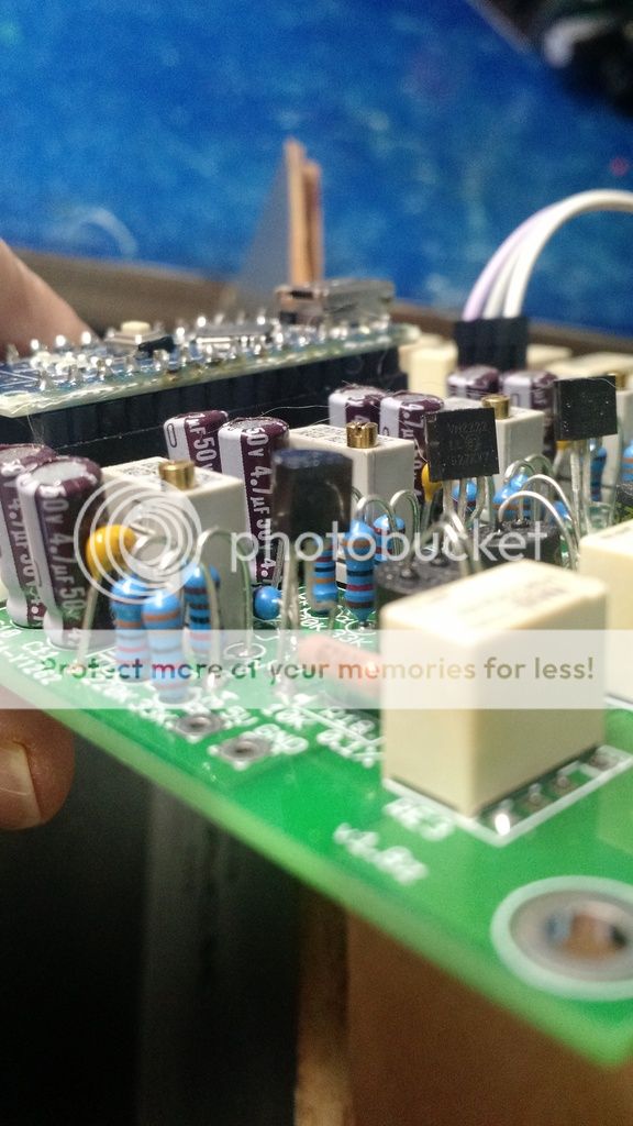
Yes, they work fine. Have to bend one lead around the other though as the pinout ids different. Not sure how much you can tell from the pic.
Yes, they work fine. Have to bend one lead around the other though as the pinout ids different. Not sure how much you can tell from the pic.
I like your solution better.. 😀
zdr,
I tried with I2C_ADDRESS 0x3C (0x3D, 0x78 and 0x7A) and it doesn't works.
I missing something ?
nounouchet
Probably😉 Use I2C scanner to search for address. Which display are you using?
Probably😉 Use I2C scanner to search for address. Which display are you using?
I use this one: Ecran OLED 1.3" 128X64 SH1106 Blanc interface I2C - Audiophonics
It works with U8g2lib but it is very slow and not very convenient.
The address is the standard address (0x3C).
Actually i use an OLED 0,6" SSD1306 and it works fine with your librairies but it is too small.
nounouchet
I use this one: Ecran OLED 1.3" 128X64 SH1106 Blanc interface I2C - Audiophonics
It works with U8g2lib but it is very slow and not very convenient.
The address is the standard address (0x3C).
Actually i use an OLED 0,6" SSD1306 and it works fine with your librairies but it is too small.
nounouchet
That one looks like it should work. Do you get a black screen or some other symptom?
Black screen.
But now it works !
I think it's the oled.begin() with the right structure in setup () which solved the problem.
nounouchet
But now it works !
I think it's the oled.begin() with the right structure in setup () which solved the problem.
nounouchet
Black screen.
But now it works !
I think it's the oled.begin() with the right structure in setup () which solved the problem.
nounouchet
This is what I have:
Code:
#define OLED_TYPE SH1106_128x64
#define I2C_ADDRESS 0x3C

oled.begin(&OLED_TYPE, I2C_ADDRESS);
is it not working for you like this?
Yes, they work fine. Have to bend one lead around the other though as the pinout ids different. Not sure how much you can tell from the pic.
Thanks for your answer, before to receive the VN2222LL, I tried the ZVNL110A it work well too, this Mosfet has a low Vgs th 0,75 to 1,5 V.
Hello everyone, and - thank you for this gorgeous project!
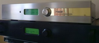
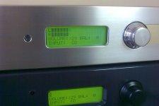
Couple of years ago, my (ex) colleagues and I did something similar to this, but it was PIC based, and LDRs had to be paired. That project was actually never 100% finished, had some bugs regarding remote control etc, and was eventually put to sleep. In the images attached you con see how it looked, back in time.
I always wanted to build one for myself (it was meant to be a commercial product, those ones we've built were sold), and just when I thought it was time to have this project awaken, I saw this thread, and now I'm completely hooked to build this version of preamp and forget about PIC, since this is the right way to do it 🙂
I'm not the programmer, though; I can see what's happening in the code, but I cannot write it on my own. So, I'll be learning along the way, and I have some questions, so be kind:
1. I have some fancy 4x20 LCD with white letters/black background, but it's not I2C, so I was wondering can it be used with your code as-is, I saw that there are some adapters for Arduino (PCF8574)?
2. Neb Zdr, many thanks for your contribution, I like your OLED version very much, did you think of implementing a VU meter, since it looks like there would be enough space on display for this feature?
Attachments
Hello everyone, and - thank you for this gorgeous project!
Couple of years ago, my (ex) colleagues and I did something similar to this, but it was PIC based, and LDRs had to be paired. That project was actually never 100% finished, had some bugs regarding remote control etc, and was eventually put to sleep. In the images attached you con see how it looked, back in time.
I always wanted to build one for myself (it was meant to be a commercial product, those ones we've built were sold), and just when I thought it was time to have this project awaken, I saw this thread, and now I'm completely hooked to build this version of preamp and forget about PIC, since this is the right way to do it 🙂
I'm not the programmer, though; I can see what's happening in the code, but I cannot write it on my own. So, I'll be learning along the way, and I have some questions, so be kind:
1. I have some fancy 4x20 LCD with white letters/black background, but it's not I2C, so I was wondering can it be used with your code as-is, I saw that there are some adapters for Arduino (PCF8574)?
2. Neb Zdr, many thanks for your contribution, I like your OLED version very much, did you think of implementing a VU meter, since it looks like there would be enough space on display for this feature?
Thanks! I2C is a must due to limited number of GPIO pins. I2C bus is used to control both port expander and display. You could add another Arduino on I2C bus just to control display, but that would be an overkill if you just want to reuse your old stuff. These big OLEDs are 20eur, so not worth it IMHO.
I am not too excited to have VU meter in there, so it won't be coming from me. Foobar is doing that already 😉
Pozdrav.
Thanks! I2C is a must due to limited number of GPIO pins. I2C bus is used to control both port expander and display. You could add another Arduino on I2C bus just to control display, but that would be an overkill if you just want to reuse your old stuff. These big OLEDs are 20eur, so not worth it IMHO.
Of course, I know all this.
Perhaps you misunderstood my question a bit, let me rephrase - could I use hd47780 display IF I put the I2C adapter chip (like this ) and use your code as-is, without changes? I have noticed that most of the 4x20 displays you search on AliExpress, for example, actually use exactly this board, so I thought - if they work, why wouldn't this...
And, this is just because I already have some displays I'd like to use.
I guess that my final version will be with OLED, but I wouldn't want it less than 2.42"
I guess that should work, i2c adapters are cheap.Of course, I know all this.
Perhaps you misunderstood my question a bit, let me rephrase - could I use hd47780 display IF I put the I2C adapter chip (like this ) and use your code as-is, without changes? I have noticed that most of the 4x20 displays you search on AliExpress, for example, actually use exactly this board, so I thought - if they work, why wouldn't this...
And, this is just because I already have some displays I'd like to use.
I guess that my final version will be with OLED, but I wouldn't want it less than 2.42"
Sent from my ZTE A2017G using Tapatalk
Hello! Does anybody have these?
- one psu board (and components/transformer)
- one IR remote receiver sensor
- one rotary encoder
Please send a PM.
- one psu board (and components/transformer)
- one IR remote receiver sensor
- one rotary encoder
Please send a PM.
Hello everyone
I discovered this thread a short time ago and am very interested in the realization of this project. I have ordered for the components and to this day I have in my possession an OLED display (0.96 - 4 pins) but one of the connections is SCK and I see on many assemblies that it is called SCL.
Is this the same connection and this display can be suitable?
Thank you. 🙂
I try order a power supply pcb to 'www.shenzhen2u.com'.
But after upload the file 'LDR ATT power supply GERBER.zip' provided on post 106, anything displayed on preview is only related to controller pcb, not PS.
Also I still not found anywhere a suitable bom parts list for the power supply.
Thanks in advanced
But after upload the file 'LDR ATT power supply GERBER.zip' provided on post 106, anything displayed on preview is only related to controller pcb, not PS.
Also I still not found anywhere a suitable bom parts list for the power supply.
Thanks in advanced
- Home
- Source & Line
- Analog Line Level
- Arduino based LDR volume and source selection controller