Hi JOIMONF,
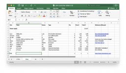
I uploaded the "LDR_ATT_power_supply_GERBER.zip" zip archive to Shenzhen2U and it worked fine. The PSU BOM was in the "LDR Controller BOM v1.8.xlsx" Excel file, second tab at bottom. I am attaching images.
I uploaded the "LDR_ATT_power_supply_GERBER.zip" zip archive to Shenzhen2U and it worked fine. The PSU BOM was in the "LDR Controller BOM v1.8.xlsx" Excel file, second tab at bottom. I am attaching images.
Attachments
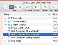
The "rev1" zip archive at post 106 is the one I used a few months ago. Seems to be working ok. Maybe there's a later version but I didn't see one when I started the project. I'm not using the I/O board, just PSU and control.
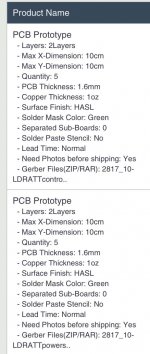
Thanks dbis, I uploaded the power supply file, but not enough, then is need filling in some requirements.
I am not confident, any further advice is welcome.
*Layers
1Layer 2Layers 4Layers
*Max X-Dimension
5cm 10cm 15cm 20cm 25cm 30cm
*Max Y-Dimension
5cm 10cm 15cm 20cm 25cm 30cm
*PCB Thickness
1.6mm 0.6mm 0.8mm 1.0mm 1.2mm 2.0mm
*Copper Thickness
1oz 2oz(1.6mm PCB Thickness)
*Surface Finish
HASLLead-FreeENIG
*Solder Mask Color
Green Red Yellow Blue White Black
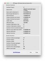
Attached below a jpg of my order. I got the original info in Autodesk Eagle. I'm attaching that "quote" info box as well. You can download Eagle for free I think. There's also a site mentioned in this thread called Mayhewlabs that has a gerber viewer, pretty cool. Just FYI I think it took about three weeks to get my boards. I chose Deutsche Post. I didn't know DP was in China. I think DP sent it to the states from China and then it was delivered by US postal service. Good luck.
Attachments
Hello everyone
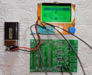
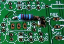
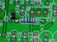
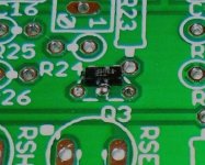
I started the realization of this project and the major problem is the unavailability of the 5LN01SP and so I chose as mentioned in replacement of the FDV301N. These components require an adapter to be set up but I tried another solution with a soldering iron that is not at all adapted but with a little patience and starting the assembly by welding them first.
Here is a detailed description of the stages but we must be sure not to have them deteriorate and a test is required.
Regard's 🙂
Attachments
Hello everyone
I started the realization of this project and the major problem is the unavailability of the 5LN01SP and so I chose as mentioned in replacement of the FDV301N. These components require an adapter to be set up but I tried another solution with a soldering iron that is not at all adapted but with a little patience and starting the assembly by welding them first.
Here is a detailed description of the stages but we must be sure not to have them deteriorate and a test is required.
Regard's 🙂
Thats really neat and tidy. Well done. Does it work ok with FDV301N?
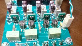
Nice!Ιn the second Volume LDR i use smd SOT23 adaptors and 5LN01C no problem at all...
I will wait your listening impressions.😉
We lost each other.😀
I read in the thread that it was a good replacement and it is mentioned in a BOM.Thats really neat and tidy. Well done. Does it work ok with FDV301N?
Attachments
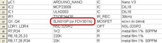
I read in the thread that it was a good replacement and it is mentioned in a BOM.
It works just fine, I'm the one who put it there😉
Thank you zdr because it allows to make a choice of transistor in replacement that works for sure .. 😉It works just fine, I'm the one who put it there😉
PS: Maybe you can answer me.
I ordered optocouplers and I received NSL-32 (not SR2 and not SR3), do you think I can mount them anyway?
Here is a detailed description of the stages but we must be sure not to have them deteriorate and a test is required.
Regard's 🙂
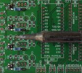
Nice job! Your iron is made by ERSA, isn't it? I've got the same tip and it works rather well for SMD purposes. But, besides my goggles, I need a magnifying lens to do the job.
Best regards!
Hello PirinhaNice job! Your iron is made by ERSA, isn't it? I've got the same tip and it works rather well for SMD purposes. But, besides my goggles, I need a magnifying lens to do the job.
Best regards!
My soldering iron is a JBC 30ST which is over 25 years of age, i still can solder without a magnifying glass but it is not easy. 😀
thank you 😉
Hi Neb,
In order to use a 1.3" IIC I2C Serial 128x64 OLED display, driver IC: SSH1106 or SSD1306
with Vincent's firmware, what changes must do in code ?
thank you 🙂
In order to use a 1.3" IIC I2C Serial 128x64 OLED display, driver IC: SSH1106 or SSD1306
with Vincent's firmware, what changes must do in code ?
thank you 🙂
Last edited:
I have Vincent's i/o board with latching relays
#define AIO //** enables AIO (All-In-One) PCB, comment out for controller only PCB
#define OLED_TYPE Adafruit128x64 // For SSD1306 OLED - exactly one type must be defined, comment out one of the two
//#define OLED_TYPE SH1106_128x64 // For SH1106 OLED
- Home
- Source & Line
- Analog Line Level
- Arduino based LDR volume and source selection controller