Yep aluminium. I guess using that method you could then mount that to the chassis. It would mean that the thermal drift would be driven more by the ambient temps rather than the internal chassis temps and all the LDRs should track each other being thermally tied.
Do you have a schematic you would care to share?
Do you have a schematic you would care to share?
Does the I2C bus need pull-up resistors? I have been getting occasional lockups and pauses. Since I connected two 2k2 pullup resistors over SDA and SCL it has been stable.
Does the I2C bus need pull-up resistors? I have been getting occasional lockups and pauses. Since I connected two 2k2 pullup resistors over SDA and SCL it has been stable.
Yes I am pretty sure it does. Our DAC is a 16 bit since I was thinking that 12 bit might not be enough precision especially at higher resistance .
Remote volume for DCB1
Hey everyone,
I posted a question on the DCB1 thread about a remote volume control for my Mezmerize preamp and Salas directed me here. Although I’m still at the DIY beginner stage (ACA, DCB1 and F5) I thought I’d give it a go. I think I’ve found most of the parts at Mouser and Digikey. I just have a few questions before I start:
1. Like several others I couldn’t find a replacement for Q1-4, 5LN01SP, so I’m ordering the surface mount version 5LN01C-TB-E. I found these adapters at Digikey. Will they work? It looks like the SDG orientation would be correct.
2. I’ve never used Arduino so just want to make sure which one I should get. I’d like to use Amazon since I have prime and could get it in 2 days. Would this one be OK? I have both Mac and Windows but it would be easier to connect the Mac laptop. Looks like the USB drivers might be problem on the Mac. Would it be better to buy directly from Arduino? Their board is $22. Quite a price difference but maybe fewer possible problems for a beginner.
3. For the PCBs, I'm assuming I just upload all the files in the Gerber zipped archives to ShenZhen2U.com. Right now I just need the PSU and Controller.
Thanks for any guidance and most of all thanks to Vincent77 for being so generous with this project. I’m excited.
This does look like a cool project. For Q1-4 it seems Zdr found this fet
Sot23 fets in action🙂

Sent from my MI 5s using Tapatalk
which apparently works. I too have failed to find 5LN01SP and its been my reluctance to order some boards. That said I am not a beginner to building audio stuff (usually pro audio recording gear) but am new to arduino which I am liking more everyday and see the great potential for audio related projects.
Yep you want an Arduino Nano. You can get them everywhere but caveat emptor as some of the cheaper made imitations have had manufacturing issues. That said I've used other Arduino imitations like the Uno with o problems. 😉
Ordering and uploading pcb's from gerber files to the fab house is pretty easy and most places give you all the direction you need during the ordering process.
Has anyone considered a group buy? I really only need 2-3 of the controller boards and 1-2 of the psu boards.
And yeah this is a cool project.
I've used the cheap chinise Nano's for a number of projects now and they are just fine other than the USB driver. The only other thing I have found is that there is not much current available on the 3.3V line as this is derived from the USB driver.
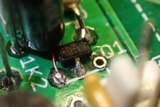
A bit crude but I managed to solder the surface mount version of the 5LN01SP driectly to the PCB. It just needed a small wire link for the source as the other pins sat between the pad and the gate resistor.
ZDR may have some PCBs available that's where I got mine from. It is an all in one PCB with 5 input relays, and a line out / headphone outputs.
When soldering in the components I would suggest leaving the legs a little longer on the LDRs this is to make it easier to hook up your probes for calibration.
Ideally if I were making my own boards
- I'd add PCB test points to the LDRs.
- Add 2K2 pull-up resistors to the I2C bus (might be an issue because of the larger display I'm using)
- Add the surface mount footprint for the transistor
Attachments
Thanks garym999. Like many others I have a slight fear of smd as I've melted a few smd components in the past but I am certain I can do it and with the pin out being fine I am confident it'll be alright. If I do have to order them I will keep your suggestions in mind.
Cheers
Cheers
Age is getting the better of my eyes now but a nice fine tip on a temp controlled soldering iron & fine solder is OK for one offs like this. If you lightly wet the a solder pad first and the place the component on the pad with a cocktail stick, a quick touch with the iron will get your first joint. Then its easy.
Thanks for all your help guys. I'm sure I'll be checking back in once I get parts and start putting things together. Just about everything is a learning experience for me right now but I'm having fun.
I got some preliminary measurements... while the is a 1% difference between calibration and measured resistance , LR difference is at 0.35%..basically LR move linearly in the same direction.
What I would try as suggested by Gary is to use a alu bar for the 4 LDRs to keep constant and equal temp.
What I would try as suggested by Gary is to use a alu bar for the 4 LDRs to keep constant and equal temp.
I got some preliminary measurements... while the is a 1% difference between calibration and measured resistance , LR difference is at 0.35%..basically LR move linearly in the same direction.
What I would try as suggested by Gary is to use a alu bar for the 4 LDRs to keep constant and equal temp.
Can you actually hear 1% resistance fluctuation?
Hey everyone,
I posted a question on the DCB1 thread about a remote volume control for my Mezmerize preamp and Salas directed me here. Although I’m still at the DIY beginner stage (ACA, DCB1 and F5) I thought I’d give it a go. I think I’ve found most of the parts at Mouser and Digikey. I just have a few questions before I start:
1. Like several others I couldn’t find a replacement for Q1-4, 5LN01SP, so I’m ordering the surface mount version 5LN01C-TB-E. I found these adapters at Digikey. Will they work? It looks like the SDG orientation would be correct.
2. I’ve never used Arduino so just want to make sure which one I should get. I’d like to use Amazon since I have prime and could get it in 2 days. Would this one be OK? I have both Mac and Windows but it would be easier to connect the Mac laptop. Looks like the USB drivers might be problem on the Mac. Would it be better to buy directly from Arduino? Their board is $22. Quite a price difference but maybe fewer possible problems for a beginner.
3. For the PCBs, I'm assuming I just upload all the files in the Gerber zipped archives to ShenZhen2U.com. Right now I just need the PSU and Controller.
Thanks for any guidance and most of all thanks to Vincent77 for being so generous with this project. I’m excited.
I think all SOT23-3 adapters have standard 2.54mm pitch, which is a bit wider than what is on board. You might need to bend legs a bit after soldering them. I am using Arduino Nano clones with CH340 USB chip from eBay which is totally plug-and-pRay. Never paid more than 2.5eur for them, and never had any issues.
For example:
http://www.befr.ebay.be/itm/181880014216
Last edited:
Can you actually hear 1% resistance fluctuation?
Me personally I cant , but there might be some people with "golden ears" that could . We all know that LDR sound better than any potentimeter on the market right now even at 4-5% skew. 1% compared to calibration is not much especially since L vs R are tracking even closer (at 1% skew LR tracks at 0.5%). Anyway still trying to find ways to achieve the lowest skew betwen LR. My target is 0.25%
Thats like using 0.1% resistors on a stepped attenuator. Not bad ..
Last edited:
Does the I2C bus need pull-up resistors? I have been getting occasional lockups and pauses. Since I connected two 2k2 pullup resistors over SDA and SCL it has been stable.
I think I had that too, but only with smaller 0.96" OLED. I just got another 2.42" OLED and will test with it. I guess it does not hurt to include some pull-ups on the pcb.
I have not tried it personnaly but it might be worth going for the NSL-32SR2S(orted) even though this unit self calibates, as they will better matched initially.
I'm sure you could compensate for temp drift using a local temp probe and can code. If you were to go for the bar then that would be the best place to fit it.
At very high resistance values with just the LDR on a breadbaord the drift is very evident.
I've spent a lot of time on the bench with this so far and as Neb suggests there comes a point where you just need to listen and live it for a bit...
... but I like fiddling so I'm considering external I2C ADC / DAC's which may help further still
I think I had that too, but only with smaller 0.96" OLED. I just got another 2.42" OLED and will test with it. I guess it does not hurt to include some pull-ups on the pcb.
Further to this I think I have found another source of hangs/pauses and possibly the cause of damage to the NANO a while back. Earth loops! Relay 3 could be wired slightly differently so that it disconnects the LDR from the audio ground and then connects it to the logic ground. As it stands, audio ground gets linked to logic ground during muting and it was me doing that when the Nano died.
I think all SOT23-3 adapters have standard 2.54mm pitch, which is a bit wider than what is on board. You might need to bend legs a bit after soldering them. I am using Arduino Nano clones with CH340 USB chip from eBay which is totally plug-and-pRay. Never paid more than 2.5eur for them, and never had any issues.
For example:
USB Nano V3.0 ATmega328 16M 5V Micro-controller CH340G board For Arduino | eBay
Thanks ZDR. I ordered the Amazon one yesterday. We'll see how it goes but I'm reassured by your and others' experiences with the clones.
Neb, I'm using a modified version of your code base. Now playing with the IR (took ages for Mouser to send the receiver) so using an alternative.
Seems to be working apart from the fact there is no repeat on Vol+/-. Should that be working? TIA Gary
Seems to be working apart from the fact there is no repeat on Vol+/-. Should that be working? TIA Gary
DAC in mV ADC in mv Measured Resistance in kilo ohms
Left Channel
673.1294346 1102 100.4
673.0717518 1102 101.1
673.0717518 1101.9375 101.1
673.0717518 1102 101
673.0717518 1102 100.8
673.0717518 1102.125 100.7
673.0717518 1102 100.6
673.0717518 1102 100.4
673.1005932 1102 100.4
673.1005932 1102.125 100.5
673.0717518 1102 100.7
Right Channel
685.8196506 1086.75 100.2
685.8196506 1086.6875 100.8
685.7908092 1086.625 100.8
685.7619678 1086.6875 100.8
685.7619678 1086.6875 100.6
685.7619678 1086.75 100.4
685.7619678 1086.6875 100.2
685.7619678 1086.75 100.1
685.7619678 1086.75 100.2
685.7619678 1086.75 100.4
685.7619678 1086.75 100.5
This is for a programed 100Kohm series resistance LR measured within 3 sec one from the other (Resistance Readings taken every 2 minutes). Unit was kept in alu box for thermal inertia . Max skew from calibrated resistance is 1.1% , LR skew is 0.4%. Next is LDR kept in alu housing and insulated from PCB. I think we can lower both skews to prob 0.8% and 0.3% (at 100Kohm) at 10Kohm it will be lower.
- Home
- Source & Line
- Analog Line Level
- Arduino based LDR volume and source selection controller