Ah, an opportinity to rant:the plotter just kept going over and over the same location
Actually this sounds like a minor flaw which could be easily eliminated, and not the result of an internal designer 'going down a rabbit hole'. In my opinion well conceived and managed internal development has a far greater chance of success than external contracting. It's just that managment LOVE to make their careers by being at the centre of a large and expensive, high-profile project. Even if it's really a stinking pile of s**t, they will have moved on to bigger an better things before that s**t hits the fan.
In my experience, management (particularly government managment) have no problem at all spending vast sums of money on outside consultants or software development, from people who have no actual knowledge of the problem domain. At the same time, they will run a mile from spending any money at all internally, when they typically have inside people who know the processes intimately, pleading to enhance or incrementally improve the system they already have, at comparatively zero cost. To managment, the success of a project is not connected with whether it fulfils the design objectives, but their own objectives to enhance their prestige, rub shoulders with the powerful or political classes, or buy that BMW.
Being Australian you might be aware of this example, which I saw play out from the inside. TAFE NSW spent almost 500,000,000 that's five-hundred-million-dollars, half-a-billion dollars, on a new student management system from SAP and other suppliers, which didnt work properly and was abandoned.
All that said and rant over, internally developing a bridge design software does seem like a (possibly dangerous) waste of time, unless there were very good reasons that the commercially available packages could not be used or customised.
Last edited:
Indeed, in principle.it's not a random exciter or a random design - they're both known upon selection, and parameters can be modelled
No, it won't. I don't have to model designs that I consider are already deficient in some way, especially if that gives me a simpler path and makes the goal more attainable. And I only need compare among designs which I consider are worth pursuing. And it's exceedingly unlikely that I will arrive at a globally optimal design in any case. I would be very happy to arrive at a 'reference design' which embodies the principles we have learnt, which others can build, and which can be compared to other designs in practice. I have not seen any argument as to why (for example) an unsupported exciter might be better, and a contender for optimality. If you believe this, then please do make a detailed analysis and share it.Your model will have to contend with a range of different/random designs otherwise you're never going to determine which is the best
Of course it is. Christian and Burntcoil are making efforts in that direction. But again, if I can mimimise the effect of the exciter upon the speaker dynamics, I will do that. As a first cut, I will assume ideal exciter behaviour, and deal with exciter non-idealities as a separate phase, if necessary.The exciter is just another element to be taken into account,
Well I think I'm on solid ground with these points, but I invite you to discuss with Burntcoil and Christian. Neither was I dogmatic about it, if you read the sentence where I said this. And finally, I think you have it backwards. I have made certain choices which are reasonable to me, and proceed down a path that I think will lead to better designs. I don't need to prove to you that your choices are sub-optimal to make my own choice. That's not dogmatism - it's common sense. If you were to discover something which invalidates my choices, I'm always interested to hear it.Forces are also not unbalanced on a well suspended exciter, and we have no evidence that the lack of a spine will affect exciter life, or add non-linearity and noise - you appear to be falling victim to the faults you ascribe to the 'other' forum .
Eucy, I know you are a good-natured chap, and I am a prickly misanthropist. But It's precisely because I feel that our approach here IS getting us somewhere, that I am protective of this more cloistered space, with it's much higher signal to noise. If you want to join us in earnest, your'e more than welcome. But 'flick-reading' the last few pages and then proceeding to instruct us upon the approach we ought to take is not a good start.
I found a set of acoustics tutorials for bempp. https://github.com/mscroggs/bempp-acoustic-tutorials
Tutorial 5 is about a loudspeaker.
The mathematical background is through the roof, but in programming terms just a few lines to do some amazing stuff.
So far, so good...


Tutorial 5 is about a loudspeaker.
The mathematical background is through the roof, but in programming terms just a few lines to do some amazing stuff.
So far, so good...

That was not my intention at all... but ok .. I'll leave this cloistered space in peaceBut 'flick-reading' the last few pages and then proceeding to instruct us upon the approach we ought to take is not a good start.
Cheers
Hi Eucy, hi PaulThat was not my intention at all... but ok .. I'll leave this cloistered space in peace
Interesting exchange (even if I haven't gone in all the details of each of your last posts). Some external eyes are always welcome to have a look out of the rabbit hole. After some weeks (months?) digging this simulation approach, I really think it is at least a good way in parallel to experiments to get a better understanding of this quiet complex system. It helps me to connect in a larger picture the different papers I collected over the 2 last years, to include the different parameters in a large picture... and the hope to come out the endless looping trial and error process. Without developing this picture, my intuition about DML is low.
About your question Eucy about free hanging exciter, there is probably a way to include it in a model. It is probably needed to have a good design of such a system. If you have some taste for scripting in Python, for equations and research... some free hours... there are possibilities. For now it is not in my priorities.
Good point you have downloaded Elmer Eucy. Paul's files are very helpful to start
Christian
https://www.diyaudio.com/community/...ll-range-speaker.272576/page-470#post-7270339That's more complicated to model, and since the spine-mounted case is better anyway, why would you bother?
Paul, Eucy,
For what it’s worth, in this particular case, I found that there was very little difference between a free mounted exciter, and a spine mounted exciter. I don’t know for sure if this True in general, or just in some specific cases. I must admit, for myself I was a little surprised at how little affect the spine seems to have.
Hopefully I linked to the right post.
Hello EricPaul, Eucy,
For what it’s worth, in this particular case, I found that there was very little difference between a free mounted exciter, and a spine mounted exciter. I don’t know for sure if this True in general, or just in some specific cases. I must admit, for myself I was a little surprised at how little affect the spine seems to have.
Hopefully I linked to the right post.
You linked to the right post I think.
2 comments :
One reason you don't see an effect of the bracing might be because it is below the LF cut off of your panel which is probably made by the self baffling of the panel. It is here where modelling is interesting. Papers evaluated the effect of the exciter magnet mass by giving a kind of lower frequency reachable. With a bracing no such additional filter. I don't remember paper showing the effect of the self baffling.
In my tests, I think one benefit of the bracing was on the distortion by limiting the "useless" displacements in LF.
The construction is then more robust as you mentioned. Just by this aspect of robustness, I don't see why not having a spine when aside the benefit of a free exciter (except for test) is not obvious.
Christian
Making slow progress with bempp. Again it's poorly documented. I'm trying the simplest thing that could possibly work (by probably not) - giving it the 2D mesh with velocity field from Elmer.
Currently sorting out how to input the mesh, because bempp reads the mesh but not the field values, so you have to read the mesh again to get them. So now I'm reading the mesh but using the (undocumented!) Grid constructor, which takes numpy arrays of vertices and elements, but the structure of each is different than expected. Now problems with the separate meshed body of the exciter, which had normals pointing in the other direction, but bempp requires all normals to point the same way.
I shall probably have to build a larger 3D model, with an identical mesh on the reverse side so that I can assign the field values there with opposite polarity, and maybe a baffle too. Then give Elmer just the segment it requires.
I dont see how to easily do an infinite baffle in bempp either so that we can compare with other methods. Building a box that's large enough in comparison with the panel dimensions would mean a mesh with many more elements, and very slow run times.
Hello PaulMaking slow progress with bempp. Again it's poorly documented. I'm trying the simplest thing that could possibly work (by probably not) - giving it the 2D mesh with velocity field from Elmer.
Currently sorting out how to input the mesh, because bempp reads the mesh but not the field values, so you have to read the mesh again to get them. So now I'm reading the mesh but using the (undocumented!) Grid constructor, which takes numpy arrays of vertices and elements, but the structure of each is different than expected. Now problems with the separate meshed body of the exciter, which had normals pointing in the other direction, but bempp requires all normals to point the same way.
I shall probably have to build a larger 3D model, with an identical mesh on the reverse side so that I can assign the field values there with opposite polarity, and maybe a baffle too. Then give Elmer just the segment it requires.
I dont see how to easily do an infinite baffle in bempp either so that we can compare with other methods. Building a box that's large enough in comparison with the panel dimensions would mean a mesh with many more elements, and very slow run times.
I am admirative to your courage to work with those tools probably powerful but hermetic!
Hello,
Just to keep inform of what is on going (slowly...) here : get the mechanical admittance at a driving point for a simply supported plate (next to come should be the FR and the electrical impedance...). The principle of the calculation can be applied to any type with for exemple the FDM after. Encouraging.


Just to keep inform of what is on going (slowly...) here : get the mechanical admittance at a driving point for a simply supported plate (next to come should be the FR and the electrical impedance...). The principle of the calculation can be applied to any type with for exemple the FDM after. Encouraging.
ChristianHello Eric
You linked to the right post I think.
2 comments :
One reason you don't see an effect of the bracing might be because it is below the LF cut off of your panel which is probably made by the self baffling of the panel. It is here where modelling is interesting. Papers evaluated the effect of the exciter magnet mass by giving a kind of lower frequency reachable. With a bracing no such additional filter. I don't remember paper showing the effect of the self baffling.
In my tests, I think one benefit of the bracing was on the distortion by limiting the "useless" displacements in LF.
The construction is then more robust as you mentioned. Just by this aspect of robustness, I don't see why not having a spine when aside the benefit of a free exciter (except for test) is not obvious.
Christian
The LF cutoff for this panel is determined by its fundamental natural frequency, I feel pretty sure. But I suspect that that for panels with a fundamental below 100 hz, there is a greater chance that the exciter itself or the mounting starts to influence the cutoff frequency.
Solved the normals issue, and finally figured out the easy way to get the data in from Elmer to bempp - its obvious when you know how :/.
Dont take notice of the numbers here, I have not even bothered to add the calc for velocity yet or get the frequency right. But is does seem to work.
It seemed to be happy enough to accept a 2D plate, and it radiates with the same sign in both directions, but that's not useful anyhow. Next I need to stitch together the front and a reversed copy for the back to get the proper polarity.
Attachments
Hello Paul.Solved the normals issue, and finally figured out the easy way to get the data in from Elmer to bempp - its obvious when you know how
I am not able to understand for the moment how you solved this issue but I am happy to see you are progressing!
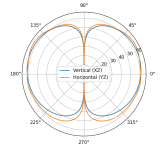
I stitched together a front and back of a panel with opposite polarity for bem measurements. Responses are as expected - a strong falloff of frequency with distance, and bipolar dispersion. Im still just using a random displacement field from some earlier experiments. Each analysis takes about 2 minutes on my laptop, so a freq response with say 50 points will take a couple of hours..
Next I have to build this code into my previous analysis code as a function for getting a reponse.
Regarding standardisation, ideally we would agree upon some standard panel area (I'm using 0.5 m^2), and standard distance for far-field (what about 4m?) and a standard excitation force or pressure (maybe 50 grams force, ~5N ?). Any suggestions for these figures, or any other things we should agree upon? Maybe damping, but that is a can of worms I think...
I will add an option to apply the body force to the whole body for harmonic analysis, because when comparing eg aspect ratio, using an exciter location will obscure the results, exciting different modes as the aspect ration changes. Better to separate optimisation of exciter location from aspect ratio etc.
So next week I hope to have the first frequency response from BEM.
Attachments
Hi PaulRegarding standardisation, ideally we would agree upon some standard panel area (I'm using 0.5 m^2), and standard distance for far-field (what about 4m?) and a standard excitation force or pressure (maybe 50 grams force, ~5N ?). Any suggestions for these figures, or any other things we should agree upon? Maybe damping, but that is a can of worms I think...
I was exactly thinking about that yesterday.
From my side as I have some CPU limitation on my current laptop, a low form factor will be better than the high (around 4) one. Dimension in multiple of 20mm would be also welcome (it is the usual step I use to avoid high CPU load). For the distance, just 4m is much above the practical distance I have but not a problem. For the force, I would suggest to take a value related to the force factor and power of an exciter (not done the calculation for now...). Let say 1W in 4Ohm and 4N/A give 0.5Aeff so 2N. In the other way 5N is 1.25A so 6.25W. why not. Or for level comparison... 2.83Veff (1W in 8Ohms) leads to 2.83N! The key point will be to compare the SPL at the chosen distance and 1m if we want some efficiency comparison (decreasing level according to the distance is not expected 6dB doubling the distance but probably 3dB, to be check in addition according to the distance). Damping... the new comer. I started with a value of 0.05 but it is really a first guess as I have no data.
@Veleric : Eric, what would be your advice?
Christian
New step achieved : first FR from simulation! Same simplified case for test : a simply supported plate
The plate is Lx = 0.4 m by Ly = 0.62 m
The mesh is Nx = 21 cells by Ny = 32 cells
with a grid dx = 20 mm by dy = 20 mm
Bending stiffness B = 3.09 Nm, Areal density µ = 0.375 kg/m²
Driving Point at 0.55 0.55
Exciter : Re = 4.0 Ohm, Le = 0.1 mH, Bl = 4.0 N/A
Point Of Observation at 1.0 m


Plausible enough to be satisfied for tonight!
Explanations of the method to come
Christian
PS : some adjustment to be made in the SPL (wrong value for the reference acoustic pressure, 13db to be added?)
The plate is Lx = 0.4 m by Ly = 0.62 m
The mesh is Nx = 21 cells by Ny = 32 cells
with a grid dx = 20 mm by dy = 20 mm
Bending stiffness B = 3.09 Nm, Areal density µ = 0.375 kg/m²
Driving Point at 0.55 0.55
Exciter : Re = 4.0 Ohm, Le = 0.1 mH, Bl = 4.0 N/A
Point Of Observation at 1.0 m
Plausible enough to be satisfied for tonight!
Explanations of the method to come
Christian
PS : some adjustment to be made in the SPL (wrong value for the reference acoustic pressure, 13db to be added?)
Last edited:
Hi Paul,I stitched together a front and back of a panel with opposite polarity for bem measurements.
Which additional operations have you on that? A simple sum of the opposite identical signal would lead to zero over all the range. Some attenuation of phase effect from the distance on the rear?
Considering the simulation i just posted, I see the testing panel I use is much smaller than 0.5m², here its more 0.25m². This comes that for my use, I have a limitation in width. 0.4m seems ok, then I adapt the height to the desired form factor. I have not considered if it is important to keep the surface constant. 2 results can varie then : the efficiency, the FR in LF if we can model the baffle effect with the front ant the rear waves.Regarding standardisation
@pway
Paul,
I just came back to your previous post with FR like #275 (now my script is able to give results in the way it outputs something, I have more possibilities to go in the comparison) In a next simulation I will import your parameters (panel 1m*0.5m, material...) to have a comparison. 2 remarks having a look back to those FR :
- have you the option of semilog (I am used to have the freq in log!)? If not, not a problem to plot in linear also from Python.
- it seems having a difference between our 2 scripts at the first frequencies.
Hi Christian
Yes I can plot semilog no problem, I’m using matplotlib. I use linear when I need to interpolate or estimate frequency values because it’s not very accurate with a log scale.
Yes looking forward to comparing bem results with simple source method (ie Rayleigh integral) and your method (modal superposition I guess?). We are travelling to the coast for the weekend, with very poor phone signal. So if I don’t reply that’s why. 39 C is predicted for Sunday, and the weather should be cooling by now. 😅
I created a copy of the front mesh displaced by 15mm back, and reversed the polarity for the rear. Then I stitched them together by creating the sides with more triangles. Yes simple Rayleigh integral cannot handle this, it’s for BEM. I can’t do double-sided with Rayleigh, and I can’t build an infinite baffle for BEM, so comparison is not like with like.Which additional operations have you on that?
About the size, I chose 0.5 because it was close to what many people have built, and a reasonable size to get some bass. It’s near the size I would be aiming at for a real build.
- Home
- Loudspeakers
- Full Range
- Application of Impulse Excitation for DML Design and Analysis