Hi
I want to clarify if i invest more time to build an amp or not..
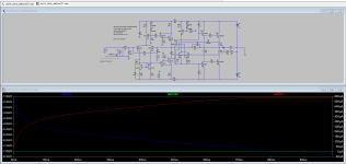
Time for simulation.
Minek show spike in the simulation at post #89
here
i have done it without D1 as dragan recommended.
for compare i use 60msec sim too.
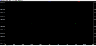
if i let the sim run longer (280sec) i do not get the spikes...is that correct?
need this amp more time = 0,3sec to warm up and be stable...or what..?
kr
chris
I want to clarify if i invest more time to build an amp or not..
Time for simulation.
Minek show spike in the simulation at post #89
here
i have done it without D1 as dragan recommended.
for compare i use 60msec sim too.
if i let the sim run longer (280sec) i do not get the spikes...is that correct?
need this amp more time = 0,3sec to warm up and be stable...or what..?
kr
chris
Attachments
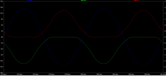
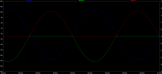
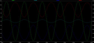
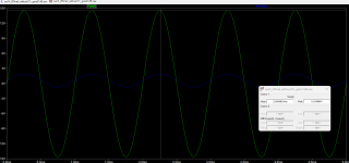
What is the idle current in both cases? Looks like for the 2nd plot, idle current is much lower.
Compare both cases with the same idle current set. I suspect that removing that diode, lowers OS idle current.
Also, these plots look like AB class to me; in class A both (upper and lower) transistors are conducting all the time.
So that means that idle current is too low to qualify this amp as class A (in both cases).
If someone wants to build class AB amp, that's OK, but that's not how this was originally designed.

Hi Minek
Thank you...yes this looks strange...
Thank you...yes this looks strange...
Attachments
Last edited:
Hi
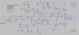
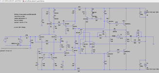
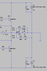
it is my bad...i am sorry...i have changed too much in the sim files therefore it is not correct working.
now i use mineks file from post 81.
remove D1 and change R5 to 2k for lower the gain. input shorted.
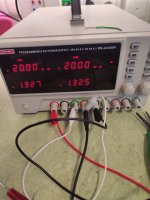
20V rail_DC offset about 13mV_bias about 1,5A
it is my bad...i am sorry...i have changed too much in the sim files therefore it is not correct working.
now i use mineks file from post 81.
remove D1 and change R5 to 2k for lower the gain. input shorted.
20V rail_DC offset about 13mV_bias about 1,5A
Attachments
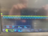
i forget to write that i use instead of 2k a 2k15 resistor at R8 -Gain is about 21dB
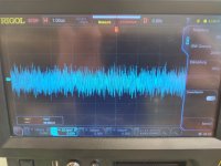
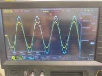
the simulation shows the oscillation too!
0,6 V input...47nF//6R --> oscillation !!
so without coil i guess this amp useless ?? 😕
the simulation shows the oscillation too!
0,6 V input...47nF//6R --> oscillation !!
so without coil i guess this amp useless ?? 😕
Attachments

Have you verified that Thiele LR network will eliminate these oscillations?
It might not be the case...
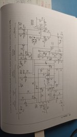
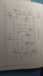
I think all these problems with this amp so far are caused by the unusual biasing circuit.
bias network...i found that
Attachments
-
 WhatsApp Image 2024-01-19 at 18.39.02.jpeg124.8 KB · Views: 77
 -
 WhatsApp Image 2024-01-19 at 18.40.25.jpeg88.7 KB · Views: 79
 -
 WhatsApp Image 2024-01-19 at 18.41.35.jpeg121.2 KB · Views: 72
 -
 WhatsApp Image 2024-01-19 at 18.42.01.jpeg169.8 KB · Views: 75
 -
 WhatsApp Image 2024-01-19 at 18.42.34.jpeg176.3 KB · Views: 76
Yes, looks good.with Zobel 0,5µH and R2 it is working
is that the correct approach?
Square waves look ok too?
😊
I have no coils in the "office" to do that...at home a have 0,5µH and 2R for sure...sorry..on the real amp
i have to look at LT file to simulate the Square.....
I have no coils in the "office" to do that...at home a have 0,5µH and 2R for sure...sorry..on the real amp
i have to look at LT file to simulate the Square.....
hm...so we have to add a Thiele network for sure...i remember prasi had done a separate PCB for that...
enough for today.
amp in simulation is with 330nF // R6 with Thiele stable..
amp in simulation is with 330nF // R6 with Thiele stable..
Attachments

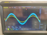
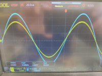
Sine test at max power 20Vrail_16,5WATT into 6R
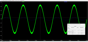
same with 220nF 10kHz okay
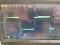
square not okay about 12,5 WATT output but 220nF is too much!!
how to calculated this thiele network for taht...i guess the 0,5µH are too less....normally about 1µH, or?
kr
chris
same with 220nF 10kHz okay
square not okay about 12,5 WATT output but 220nF is too much!!
how to calculated this thiele network for taht...i guess the 0,5µH are too less....normally about 1µH, or?
kr
chris
Attachments
- Home
- Amplifiers
- Solid State
- Apex AA14 Amp Class A 24V Supply