Sandy, once again I am amazed at your resourcefulness. You consider everyone the Taliban, or at best monkeys with a grenade.
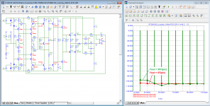
I brought your scheme 1:1 with the settings of the modes indicated on your scheme.
It turns out that if your circuit works worse than another circuit, then anyone but you is to blame, the monkey with the grenade should adjust your circuit so that it works better than it really is!
I was hoping you could read graphs, but you can't even do that.
On the chart, all operations are signed (circled in red). As you can see, arithmetic for the first class.
p.s.
fagos, explain to Sandy, otherwise he does not understand elementary things
Attachments

Last edited:
Moreover, there is a branch where for 10 years they tried to find out which parameter correlates with sound quality.
https://www.diyaudio.com/community/threads/sound-quality-vs-measurements.200865/post-2834758
Only one participant indicated which amplifiers his wife instantly determines by ear that they sound right. And indeed, in his opinion, and not only, they sounded better than many famous brands.
I became interested in this phenomenon and modeled the circuits of these amplifiers. It turned out that the amplifiers do not shine with ultra-low distortion, but they completely lack SID distortion (or as I call them “high-speed distortion”). Otala and Walt Jung called them rotation distortions (distortions that occur when a signal deviates from a pure sine wave in any way as a result of a change in either the amplitude or frequency of the signal, which is the case all the time in a real music signal!) 🙂
Well, what you write is not true at all.
You didn't set the currents to be like in my scheme at all.
At least monkeys can see well.
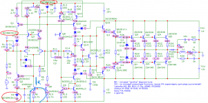
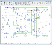
The zeners for me are 6.2V on this scheme, you can't see what they are and they are low voltage.
The current of the input stage is 2.5mA for me, and 1mA for you.
The VAS current for me is 5mA, for you it is 1.37mA.
I have a quiescent current of 25mA for a total of 100mA
You did it at 50mA for a total of 200mA
You need an eye doctor too!!
Let me see what the currents are on your circuit because it doesn't show what the zener diodes are either.
Yes, that's what I wanted to see, how exactly do you do the trial setup for Speed distortion!
And I won't say that a monkey with a grenade did it, so as not to offend the monkeys.
Could you not understand that the phase shift of the amplifier is not compensated by a delay line because it is not caused by one.
And either you take the output before the RL circuit, or on both amplifiers you put the same LR circuit in the output.
This is an honest comparison from a person who has basic knowledge of electronics.
And I already said I don't comment on who likes what sound.
Dung beetles like one food, I like another.
But these are not objective criteria and therefore such things cannot be compared.
They are discussed with fans with the same taste, or with the personal psychiatrist.
You didn't set the currents to be like in my scheme at all.
At least monkeys can see well.
The zeners for me are 6.2V on this scheme, you can't see what they are and they are low voltage.
The current of the input stage is 2.5mA for me, and 1mA for you.
The VAS current for me is 5mA, for you it is 1.37mA.
I have a quiescent current of 25mA for a total of 100mA
You did it at 50mA for a total of 200mA
You need an eye doctor too!!
Let me see what the currents are on your circuit because it doesn't show what the zener diodes are either.
Yes, that's what I wanted to see, how exactly do you do the trial setup for Speed distortion!
And I won't say that a monkey with a grenade did it, so as not to offend the monkeys.
Could you not understand that the phase shift of the amplifier is not compensated by a delay line because it is not caused by one.
And either you take the output before the RL circuit, or on both amplifiers you put the same LR circuit in the output.
This is an honest comparison from a person who has basic knowledge of electronics.
And I already said I don't comment on who likes what sound.
Dung beetles like one food, I like another.
But these are not objective criteria and therefore such things cannot be compared.
They are discussed with fans with the same taste, or with the personal psychiatrist.
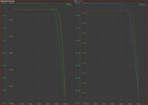
AC characteristics!
I made a comparison with mongo on a good CFA amplifier, you offer me some very mediocre scheme for comparison.
I made a comparison with mongo on a good CFA amplifier, you offer me some very mediocre scheme for comparison.
Attachments
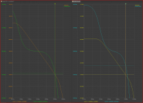
THD
For an easy comparison, there are also the numerical values of the two schemes.
Up on the specific shed, down on the competitor.
THD at R of the signal source 22k
The spectrum is at 10KHz at 35V in the output 90% of the maximum power.
For an easy comparison, there are also the numerical values of the two schemes.
Up on the specific shed, down on the competitor.
THD at R of the signal source 22k
The spectrum is at 10KHz at 35V in the output 90% of the maximum power.
Attachments
Last edited:
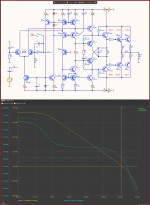
And finally, Graham Maynard's FCD test. This test is in perfect agreement with the “Taliban” Matti Otala's statement that the first pole should be at least above the audio range.
Only in this case, the loop gain has no phase shift responsible for distortion in the time domain and the output impedance of the amplifier is constant over the entire audio range.
Only in this case, the loop gain has no phase shift responsible for distortion in the time domain and the output impedance of the amplifier is constant over the entire audio range.
Attachments
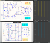
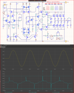
Sandy, I wanted to do the best for your circuit - I increased the quiescent current by 2 times to reduce switching distortions, which are significant at a current of 25 mA. I hope you understand that switching distortions also make a significant contribution to the spectrum of higher harmonics. If I had not increased the quiescent current, the parameters of your amplifier would have been much worse!
As for zener diodes, as you can see, all zener diodes are 6.2 V each. But for them to work in stabilization mode, the documentation specifies their minimum current, you don’t seem to know this.
p.s.
it’s hard to talk with Napoleon who seems to be around either the Taliban or monkeys with a grenade
As for zener diodes, as you can see, all zener diodes are 6.2 V each. But for them to work in stabilization mode, the documentation specifies their minimum current, you don’t seem to know this.
p.s.
it’s hard to talk with Napoleon who seems to be around either the Taliban or monkeys with a grenade
Attachments
What is your current and what is Sandy's? Judging by the diagram, Sendu has a higher current than you have in your model, right?As for zener diodes, as you can see, all zener diodes are 6.2 V each. But for them to work in stabilization mode, the documentation specifies their minimum current, you don’t seem to know this.
for the zener diode used in the circuit, the minimum current is generally 1mA, another thing is such a stabilization parameter as internal resistance and the dependence of the stabilization voltage on temperature.
The optimal value for a zener diode is 6.2 volts, and not the minimum value, as you say, 5mA, but you need to take into account the peculiarities of using it in a circuit, more precisely, the influence of temperature and current consumption of devices for which it stabilizes voltage.
I'm not clever like Napoleon!
I'm just not blind and stupid!
You reduced the current on both the input stage and the VAS by 2.5 times 2.7k instead of 1.1k
But you left the same frequency correction which reduces the voltage rise rate by 2.5 times.
I have no claims that you increased the current of the final transistors, I just wanted to know that the quiescent currents of the two circuits we are comparing are the same, regardless of what they are.
Because we are comparing CFA with VFA and not class A with class AB or even B!!
The point is that you are purposely making my scheme worse by thinking that I won't see it to show that your terrible scheme is better.
Compare the new VFA circuit which is already with the same supply voltage, the same number of final transistors and currents through them, and with the same RL circuit at the output.
And then you can cry freely. 😉
Keep Otala's nonsense for your own use.
Compare not the modified amplifier you designed to make it worse, but compare the schematic I made, which is identical in gain and output power to yours.
Attachments
Last edited:
for the zener diode used in the circuit, the minimum current is generally 1mA, another thing is such a stabilization parameter as internal resistance and the dependence of the stabilization voltage on temperature.
The optimal value for a zener diode is 6.2 volts, and not the minimum value, as you say, 5mA, but you need to take into account the peculiarities of using it in a circuit, more precisely, the influence of temperature and current consumption of devices for which it stabilizes voltage.
Hennady, you are correct...
Yes, I admit that I incorrectly installed one resistor R7 (2.7 kOhm instead of 1.1). Replaced, now all the currents are in place, But did the amplifier work better from this? (see test!). 🙂
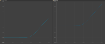
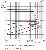
I’m just amazed how a person who positions himself as a cool Guru in electronics and who made a ring stabilizer wants to have a current > 5 mA through a 2.7 kOhm resistor R11 with a voltage drop across it of only 5.5 V. The maximum that such a stable current generator can produce it's 2 mA. But at the same time, the zener diodes will have a high dynamic resistance and the voltage drop across them will be less than 6 volts (see graph).
Attachments
petr_2009, Hennady,
A current of 2mA is chosen for the zener because the power supply is +/-85V=170V
The dynamic resistance of the zener diode in this case is not important because here they are not fed in the stupid way with resistances as in the diagrams shown by petr_2009, but through current generators.
And precisely so that these transistors do not heat up a lot, a current of only 2mA is chosen (157V*2mA=0.3W)
The temperature coefficient of the zener is also not so important in this case.
Even if we want a really temperature-stable current, we need a completely different 3.9-4.7V zener to compensate its temperature coefficient with that of the transistor. But then the output resistance of the current generator becomes worse.
But anyway, such things are pointless.
Flat one-dimensional thinking does not work, and even two-dimensional thinking does not work.
You need 3D thinking, many things are interconnected and if a person has little experience and negative knowledge, fixing one not particularly important thing can spoil 3-4 other important things.
Reducing the voltage rise rate by 2.5 times is important!
Reducing the feedback depth by 2.5 is important because it raises all distortions by 2.5.
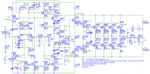
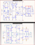
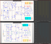
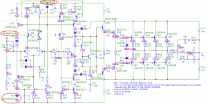
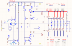
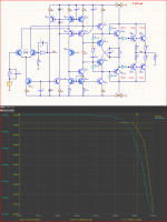
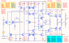
Here is a VFA with a BJT input and a diamond buffer and with VAS h22b compensation.
Due to the greater steepness, we can pass without amplification in the entrance step.
The input and VAS are one stage broken cascode.
However, the result is generally worse, although not as drastically worse as that of the CFA amplifier.
(The pulsed signal test found increasing the capacitor in the frequency correction from 75pF to 100pF.)
Attachments
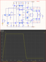
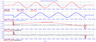
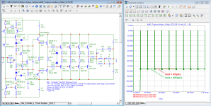
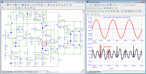
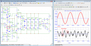
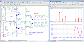
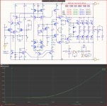
There you have it, your favorite method of displaying THD, but done right, not with a delay line.
To keep things correct, we use the same 1k/100pF RC group at the input of the compensation circuit, so there is no need to remove the capacitor at the input, because it also affects the frequency correction of the amplifier, albeit slightly.
The delay of the amplifier (phase rotation) is compensated not by a delay line but by an accelerating RC circuit.
C9=0.52pF which with R28=30k gives a frequency of 10MHz which is approximately the bandwidth of the amplifier without the input RC circuit (1k/100pF)
And as you can see, Speed distortion is completely missing because it is the result of the stupid use of a delay line for compensation.
Peak error is +/- 0.7mV based on +/-60V at the output is 0.0011%
It matches very well with the 0.00088% eff error obtained from the FFT analysis.
Attachments

Replacing the resistors with current generators does not affect the parameters.
If you could think, you would first make a check and compare the two variants in the simulator, with resistances and with current generators.
And then you wouldn't expose yourself by writing nonsense.
I deliberately made it with current generators, because otherwise you don't understand where and what kind of current should be there.
The problem is that the new version of Altium AD22 no longer shows THD as a number, so to see the numbers I do this simulation in AD19.
But for him, this scheme is too complicated and the simulation does not start when there are resistances, instead of current generators
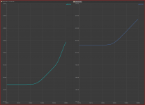
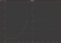
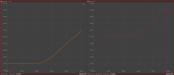
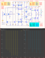
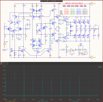
And especially for prodigies with a large negative intelligence, a comparison of the two options.
Yellow graphic with generators and current
Blue graphic with resistors.
A difference of 3dB for PSRR is not much of a problem for me.
There is also a difference in THD only at harmonic 2 (20KHz) of only 3dB. The rest of the harmonics are the same.
It's just only in the AD19 that I can see the THD as numbers.
And thus it is better to compare the differences at different frequencies and loads.
So the comparison is adequate because all measurements are with current generators
I understand well that you are wondering what to object to.
But due to technical illiteracy, you can't make it something important, and you get caught up in non-essential trifles. 😉
Attachments

Last edited:
dadod,Now finally, you can be rude to each other, as no one more is participating this fanny thread.😳
Since you are not participating in the topic, how did you know that we are rude.
And those who do not participate in the topic do not write in it. 🙂
It is very difficult to be honest, to tell someone the truth and not be rude.
The interesting thing is that I am accused of being rude, but no one claims that I am lying.
People only get offended when you tell them an inconvenient but true truth that they can't refute.
That's why I never take offense at anyone.
If something said by someone about me is true, why should I be offended.
And if it is not true, I accuse him of simply lying, I ask him for evidence of his claims.
I can be petty and make up problems too.
But it would be very, very stupid.
Although in this scheme, replacing the current generator with a resistor as it will in practice will not degrade the PSRR by 3dB, but will degrade it significantly more.
It is no accident that in my scheme only the resistors have been replaced with current generators, although it could have been made even simpler by removing the transistors as well. But since then the difference would have been bigger.
There are simply acceptable and unacceptable trade-offs.
But in order to be able to distinguish between them, you need theoretical knowledge, not sick fantasizing and inventing non-existent problems.
Attachments
Last edited:
- Home
- Amplifiers
- Solid State
- Apex A40 fundamental improvement. (Sandy)