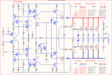
This with the models is a rather unclear matter.
T2, T4 are the last models of ON since 2004
T3, T6 are the last models of ON since 2017
Practically almost the same Ckb/Cbe and yet big differences.
Bulgarian analogues of BD135/BD136
T2, T4 are the last models of ON since 2004
T3, T6 are the last models of ON since 2017
Practically almost the same Ckb/Cbe and yet big differences.
Bulgarian analogues of BD135/BD136
Attachments
Is this the amplifier you demonstrated at the exhibition?While you are once again practicing stupid storytelling, my works have already managed to visit the audio exhibition at the end of October...
I don't care about your verbal litter...
servos for audio amplifiers don't make it the way you're trying to design it, but for the model and your stupid theoretical reasoning, it'll do...
In my opinion, an absolutely illiterately designed amplifier, moreover, inoperable!
https://forum.vegalab.ru/showthread.php?t=87882&p=2790971&viewfull=1#post2790971
Attachments
And why did you drag this into the topic of modifying the Apex A40 amplifier? I understand that you don't care where to trash, but show respect to other participants in the discussion. Declare your attitude to the Hennady Kovalsky amplifier in your personal topic that the moderators have created for you.
petr_2009,
The fact that a person has little experience and knowledge in the field of electronics does not mean that he cannot show your nonsense in the schemes you show.
Using 2 RC circuits in the offset circuit is a mongo bad idea, the low frequency dephasing becomes large and there is a risk of self-excitation or long offset settling time with long decaying speaker jitter.
And adjusting the offset through the input of the amplifier is another nonsense.
If this input is connected to a potentiometer what will happen to the offset while we turn the potentiometer???
Attachments

where do you see a discussion of the APEX-40 modification here? There has long been anything except APEX-40, and almost on ideal transistors for which no correction is needed. Everything works without correction in some simulators🙂And why did you drag this into the topic of modifying the Apex A40 amplifier?
It is not uploaded here according to a bad scheme than that of Adeev.
To be fair, I explain what is wrong with her.
You and Adeev can't even adjust the DC modes of the transistors so that they work live and not only in the simulator.
The current of Q5/Q3 only God knows how much it will be...!!!
Q12/Q11 current too.
And when it already works and Q12/Q11 heat up, and Q9/Q10 cool down, what will happen to the quiescent current of the final transistors???
And the current of Q9/Q10 when working always decreases, but hardly a person like you and Adeev understand such simple things.
And I will not comment on this nonsense with a 5V galvanically separated voltage source instead of 2 current generators.
I understand that due to technical illiteracy you cannot adjust the frequency correction according to your models.
Upload the models of the transistors and diodes you use for my circuit and I will make the necessary frequency correction with them as well.
But frequency correction is not the value of just one capacitor.
It also includes the base resistances of the final and pre-final transistors.
Last edited:
no, not this one, this one it's just a modelIs this the amplifier you demonstrated at the exhibition?
Maybe, like your theoretical crafts ...In my opinion, an absolutely illiterately designed amplifier, moreover, inoperable!
however, I have photos of finished products - you don’t have them and never had ...
Last edited:
Petr_2009q
The problem with you is that not only do you not understand anything about electronics, but that you are incapable of understanding anything about this matter.
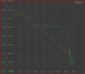
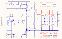
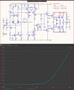
Here is the difference at 3.3 and 51 ohms R14/R15 on this circuit at C2=10pF
Electronics is not for people deprived of a lifetime of logical thinking 😉
The problem with you is that not only do you not understand anything about electronics, but that you are incapable of understanding anything about this matter.
Here is the difference at 3.3 and 51 ohms R14/R15 on this circuit at C2=10pF
Electronics is not for people deprived of a lifetime of logical thinking 😉
Attachments
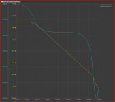
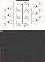
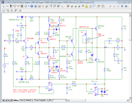
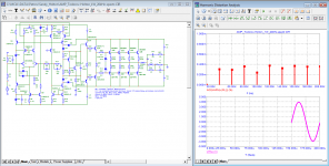
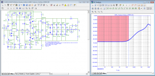
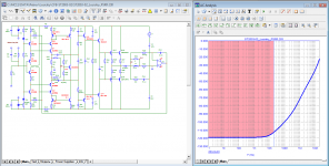
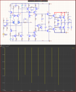
Comparison of CFA and VFA amplifiers with identical supplies and quiescent currents.
To see how stupid it is to use CFA circuits in audio!!!
4 more transistors for bad results.
Even the presence of h22 and Ckb compensations do not save the situation of CFA!!
In order to compare more easily at the lower end are the data of the competitive scheme.
The spectrum is at 60Vmax at the output of a 4ohm load and 1KHz. Yellow - VFA Red - CFA.
(Audio-P FET 1-1-3.4 V2.2 3D) is 3D and only opens with Adobe Acrobat
Attachments

Last edited:
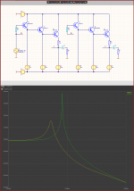
Especially for the audio talibans, who, because they can't think, fantasize about things in electronics. 😉
The input resistance of an emitter repeater is inductive (L) in nature, and with the parasitic capacitances of the transistors it becomes an LC circuit. Which can make the emitter repeater gain quite large Ku>>>1.
With the base resistors, we reduce the Q factor of this circuit in order not to allow Ku to become greater than 1!!!
Naturally, petr_2009 does not understand these things and therefore it is impossible for him to make a basic frequency correction of an amplifier.
Attachments
Sandy, your statements about the unsuitability of CFB amplifiers for sound are not true. The other day I listened to Mark Alexander's amplifier on a modern element base. Sounds great. Many companies make amplifiers with about 50/50 VFB and CFB, such as Accuphase, Marantz and others.
As for your next craft VFB, there is nothing new in it that could provide the technical parameters necessary to provide high-quality sound amplification. OPS - a typical Darlington "triple" circuit, VAS similar to Holton's structure, is used in many Yamaha amplifiers, in some Onkyo, Sony and others amplifiers.
Even the virtual model does not meet the requirements of the simplest SWDT test.
Well, as for your rudeness in communication, there is no limit to it. I'm surprised you haven't been banned from this forum forever!
your statements about the unsuitability of CFB amplifiers for sound are not true.
All the same, they correspond to reality, because In amplifiers with CFA, the values of the feedback resistors are involved in the formation of the amplifier correction, i.e. current FB is frequency-dependent on the ratings of the resistors themselves. In the VFA amplifier, there is no such dependence in the feedback circuit. If we take into account that for audio amplifiers, the frequency of a single unit, in principle, is not needed above 10 MHz, then the use of amplifiers with CFA, becomes a kind of fetish, where the ratings of the current feedback elements can even depend on the complex load.
What is the point in such a decision? win at unity gain frequency above 10 MHz? This is only possible if only 1 cascade is amplified even with a multi-stage solution topology, you see how Sandu got worried as soon as I added the second pole to CFA ))))...
Comparison of CFA and VFA amplifiers with identical supplies and quiescent currents.
To see how stupid it is to use CFA circuits in audio!!!
4 more transistors for bad results.
Even the presence of h22 and Ckb compensations do not save the situation of CFA!!
It's not the first time I've read something like this from petr_2009 and I'm not very surprised. A person does not see the semantic difference between statements and understands them distorted. Sandy says that CFA has no advantages over VFA and there is an unjustified increase in the number of elements, and petr_2009 reads "CFA is unsuitable for sound". These are real problems with the perception of information.Sandy, your statements about the unsuitability of CFB amplifiers for sound are not true. The other day I listened to Mark Alexander's amplifier on a modern element base. Sounds great. Many companies make amplifiers with about 50/50 VFB and CFB, such as Accuphase, Marantz and others.
"To argue with a man who has renounced the use and authority of reason, and whose philosophy consists in holding humanity in contempt, is like administering medicine to the dead, or endeavoring to convert an atheist by scripture." ― Thomas Paine
Petr_2009,
Don't attribute things to me that I didn't say.
I said CFA only has one advantage over VFA, the high but unnecessary ramp rate.
In all other parameters THD, PSRR VFA amplifier can be made with better parameters.
And I showed you 2 schemes for comparison.
As a CFA scheme it is about the maximum that can be obtained.
While from the VFA schemes, even more dynamic parameters can be obtained using positive feedbacks such as are used in the CFA of the scheme shown.
Who likes what things is already a very subjective thing, and that's why I don't comment on such things.
Everyone has the right to like what they want.
Some like small distortions, others like large but pleasant distortions.
I only comment on technically objective measurable things.
And I've always said that in modern schematic engineering, if you don't do stupid things, everything becomes listenable, as long as it's listened to by normal people without a sick imagination.
And the schemes discussed here are simply a sporting passion, and an occasion to learn more about electronics and its possibilities.
Otherwise, things are simple.
Upload a circuit of a CFA amplifier with higher parameters than the one of the VFA that I uploaded, and then I will admit that CFAs are better.
Because I can also upload another VFA scheme with even higher parameters than this one.
I have uploaded this one in the Bulgarian forum as a complete development with circuits and boards so that even people with little experience can make it.
The topic is: Simple amplifier with good sound
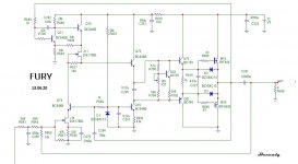
In order to compare, I showed you a diagram of an ordinary standard amplifier, simply with reasonably selected transistors, and operating modes.As for your next craft VFB, there is nothing new in it that could provide the technical parameters necessary to provide high-quality sound amplification. OPS - a typical Darlington "triple" circuit, VAS similar to Holton's structure, is used in many Yamaha amplifiers, in some Onkyo, Sony and others amplifiers.
To see that even a very good CFA amplifier cannot reach such THD and PSRR as can be achieved with a simple VFA amplifier.
Upload a circuit of a CFA amplifier with higher parameters than the one of the VFA that I uploaded, and then I will admit that CFAs are better.
Because I can also upload another VFA scheme with even higher parameters than this one.
https://www.diyaudio.com/forums/sol...-interview-negative-feedback-post1272373.html
Curl:
“Let me assure you that 'low enough' distortion figures were made decades ago by makers of Japanese and American audio equipment. If you don't listen seriously, and only read graphs, the job was done long ago.
Still, designers keep working on making better sounding amps.”
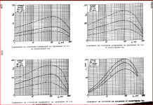
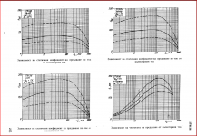
For comfortable listening to music at home, only 1 watt is often enough power. Therefore, those who know a lot about amplifiers first of all check the quality of the amplifier at an output power of 1 watt. At a load of 8 ohms, this is 4 V (peak). At a load of 4 ohms, the output power will be 2 watts, respectively.
For comparison, I take the amplifier of 2002 (author Lozitsky) made according to the classical scheme of amplifiers with current feedback.
Let's compare parameters such as SRPP, the spectrum of distortion products at a frequency of 20 kHz with an output power of 2 watts, and SID distortion at a frequency of 10 kHz.
Attachments
-
 01_Sandy-Holton_1W_20kHz-spectr.png32.5 KB · Views: 118
 -
 01_ST2003-02_Lozickiy_1W_20kHz-spectr.png33.3 KB · Views: 110
 -
 02_Sandy-Holton_PSRR.png31.1 KB · Views: 127
 -
 02_ST2003-02_Lozickiy_PSRR.png33.3 KB · Views: 114
 -
 03_Sandy-Holton_10kHz-SWDT_30Vp.png16.6 KB · Views: 114
 -
 03_ST2003-02_Lozickiy_10kHz-SWDT.png16.2 KB · Views: 114
Sandy, according to what seven parameters is it necessary to select 4 pairs from hundreds of transistors so that they sing in chorus, and not like the first singers who come across singing at random ...
petr_2009,
Your comparison as always is incorrect.
The question is, are you really that technically illiterate and just don't understand what you're doing, or do you think you're dealing with fools that you can easily fool??
You can see that I have written the operating currents of the transistors of the circuit everywhere.
This is because with other models they will naturally be different and anyone who wants to try it in his simulator should set the same currents and make the exact frequency adjustments with the same phase margin.
However, it is not clear anywhere on your schematics what currents were used.
And by changing the current at the end points, I can make the circuit at 1W output power work in class A and, accordingly, have a small THD.
For the PSRR simulation, you get a prize for the biggest cheater on the forum.
You don't think I'm blind, do you, and I won't notice that on your circuit you supply AC only to the final transistors, but on mine you supply it to all transistors, both final and input.
Thus comparisons are not made!!
Also, the two circuits must be equalized in terms of supply voltage and power.
That is, remove from my circuit two terminal pairs, and heat it with +/-40V.
Or do the opposite, add more ends to yours, and feed it with a higher voltage.
Both circuits must have the same quiescent current of the final transistors.
And stop with those stupid Speed distortions, I explained that they exist only in your simulator thanks to an incorrect experimental setup.
Be so good when you show them as a graph to show the schematic of the experimental setup so we can see how you subtracted the input signal from the output signal and how you compensated for the phase shift (or delay time, if that's more understandable to you).
Also, how did you remove the harmonics above 100KHz from the sine packet?
All this should be visible on the diagram!!!!!
If a circuit is cleverly designed, the selection of transistors is not necessary at all.
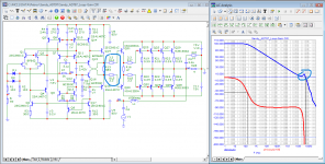
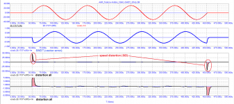
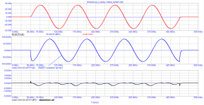
Here is a special for prodigies.
PRSS measured by the stupid method, fed variably to the final transistors only.
And THD at 2W into a 4 ohm load.
And for information only 4Vmax at 4 ohm decoction gives 1Amax which makes 2Weff and not 1W!!!
Naturally, I will also put your circuit in the simulator with the same modes and transistors and I will upload a real comparison, not fabrications and lies.
Attachments
- Home
- Amplifiers
- Solid State
- Apex A40 fundamental improvement. (Sandy)