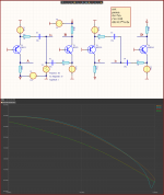
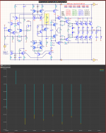
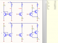
See the differences between transistors suitable for VAS
I use KSA1381/KSC3503 although in practice with BF420/BF423 the results will be better.
Because the purpose of simulations is not to brag, but to understand what how and why!
At lower power supply, 2N5401/2N5551 are good
MJE340/MJE350 are a bad idea.
BD139/BD140 are a particularly bad idea even for a common base circuit like in this example.
Here, the example simulates a common-base circuit with an input stage with a slope of 10mA/V
For example, a broken cascode.
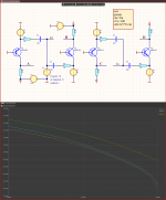
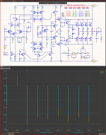
Attachments


It is very difficult to be honest, to tell someone the truth and not be rude.
The interesting thing is that I am accused of being rude, but no one claims that I am lying.
And if it is not true, I accuse him of simply lying, I ask him for evidence of his claims.
But in order to be able to distinguish between them, you need theoretical knowledge...
Sandy, you are sure that you are telling the truth, but this does not mean at all that your truth is the ultimate truth.
From the very beginning, I drew your attention to the importance of the frequency of the first pole, which Matti Otala drew attention to 60 years ago, but for you this is nonsense, because in your truth he is just Talib.
Look at the circuit of the Harman Kardon HK-990 amplifier, its first pole is above 100 kHz, and in your circuits it is below 100 Hz, like in most operational amplifiers that were not designed for audio applications at all. Information for thought.
I cited as an example Rotel amplifiers made according to the simplest circuitry and they do not use output inductances that adversely affect sound quality, but for you this is another stupidity because it does not coincide with your "truth".
By the way, there are no distortions like SID in them, which I tried to pay attention to.
https://salonzvuka.by/novosti/bowers-wilkins-600-i-rotel-a11-poluchili-nagradu-eisa
I am also leaving because I do not have the sign language to continue a conversation with a deaf person.
the frequency of the first pole correlates with the feedback depth at 20kHz.From the very beginning, I drew your attention to the importance of the frequency of the first pole, which Matti Otala drew attention to 60 years ago,
What is the depth of negative feedback?Look at the circuit of the Harman Kardon HK-990 amplifier, its first pole is above 100 kHz,
thanks, they use progressive correction!!!I cited as an example Rotel amplifiers made according to the simplest circuitry
Your problem is not technical but medical.
You don't answer any substantive questions, you just repeat the same things like a parrot.
But the problem is that both you and the parrot do not understand what you are saying.
How many times and in how many ways must it be explained to you that the Speed Distortion (SD) invented by you is nothing but an amplitude-frequency characteristic measured in the most stupid way.
Yes, a 100MHz amplifier will have smaller SDs than a 10MHz one, and both will be better than a 1MHz one.
A sine wave has harmonics to very high frequencies.
An RC group with a cutoff frequency of 100KHz does not eliminate them completely, it just reduces their amplitude.
at 1MHz 10 times at 10MHz 100 times at 100MHz 1000 times.
But if we observe SD 1mV at 50V output, this is 50000 times smaller.
By subtracting from the input spectrum (which is wider) the one in the output of the amplifier, which is narrower than the output of the amplifier, approximately above 1MHz, everything is silo-amplitude, then we will see the rest of everything above 1MHz.
In your pictures it is a peak at the beginning and end.
But this is the result of using a delay line that delays all harmonics by the same time and does not change their amplitude.
Normal tech-savvy people who can think simply measure amplitude-frequency response.
Answer atleast once do you agree with this SD explanation and if not why ??
Because I see that as an orthodox Taliban you continue to exploit this method!
What the first pole should be with is the same nonsense that you cannot prove or explain with mathematics.
The experiment that it doesn't work is mongo simple, but naturally you can't do it because you will expose yourself again.
On the same amplifier with a frequency of the first pole 10-100Hz, just put in parallel the rectifier capacitance of about 100pF, a resistance of 16k to hell become a 100KHz pole and measure or simulate the THD of both amplifiers.
And show here the result for us all to laugh.
And because I know you won't!!
The result may not be clear for a carpenter, for example, who, due to his profession, is very far from electronics.
The problems start when carpenters start working with electricity and electricians with carpentry.
The result may not be clear for a carpenter, for example, who, due to his profession, is very far from electronics.
The problems start when carpenters start working with electricity and electricians with carpentry.
Attachments
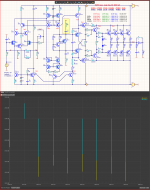

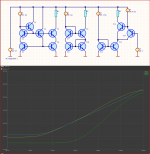
Here are your Speed Distortions without any amplifiers and without any feedback.
One RC circuit emulates a bandwidth amplifier, 1MHZ (1k/160pF)
The other RC circuit mimics a bandwidth amplifier, 10MHZ (1k/16pF)
The result is a misunderstanding of what an RC circuit with its phase shift (delay) is, and what a delay line is.
And here we are not talking about ignorance from an amateur, because from a person who does not know something, finds literature, reads it, understands it, and learns it.
Here the problem is already medical, the inability to understand and learn anything at all, and to simply memorize things and repeat them like a parrot.
Attachments
When experiments don't go to plan........ 24 pages ''poems'' and other extras: . Don't expose yourself.
. Don't expose yourself.Why do you rely so much on Otala's works, but do not read the works that follow later? Bruno Putzeys in his interview also talked about TIM and his reasons, in addition, there is also a more voluminous article by him "The F-Word or, why there is no such thing as too much feedback". At a minimum, this is alarming selectivity. And I will tell you straight out, as I have always said, you use only those facts that are convenient for you and fit your theory, bypassing the rest like underwater reefs and pretending that they do not exist.From the very beginning, I drew your attention to the importance of the frequency of the first pole, which Matti Otala drew attention to 60 years ago, but for you this is nonsense, because in your truth he is just Talib.
Why did you decide that operational amplifiers are not suitable for audio applications? They are everywhere in audio equipment, including the highest quality, proving the opposite. I am now talking about really high-class professional equipment, and not about Hi-End, shrouded in a veil of esotericism and mysticism.Look at the circuit of the Harman Kardon HK-990 amplifier, its first pole is above 100 kHz, and in your circuits it is below 100 Hz, like in most operational amplifiers that were not designed for audio applications at all. Information for thought.
And here I apparently missed something during the discussion. Where did you show Rotel and what is the scheme there? It's not clear what it's all about...I cited as an example Rotel amplifiers made according to the simplest circuitry and they do not use output inductances that adversely affect sound quality, but for you this is another stupidity because it does not coincide with your "truth".
By the way, there are no distortions like SID in them, which I tried to pay attention to.
https://salonzvuka.by/novosti/bowers-wilkins-600-i-rotel-a11-poluchili-nagradu-eisa

It's not just about displaying images, you have to say what exactly is optimized and by how much.
Putting in a lot of stuff just to make things worse is not optimization.
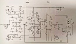
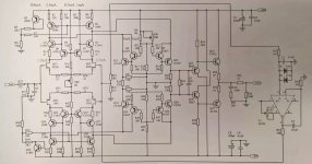
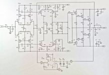
I am talking about schemes P40-2022, P41-2022. Their author does not understand much about electronics.
The WRJ-HT is relatively good, but it needs a makeover to make it better.
Is there any technical data about the THD, PSRR achieved with these schemes...??
The OP-1000 Sandy 4EP uses the same h22b compensation methods, but they work correctly, unlike the WRH-HT.
And when you show the scheme, show what it can do and what its parameters are.
Here people are mostly amateurs and cannot judge how mediocre a scheme is.
Putting in a lot of stuff just to make things worse is not optimization.
I am talking about schemes P40-2022, P41-2022. Their author does not understand much about electronics.
The WRJ-HT is relatively good, but it needs a makeover to make it better.
Is there any technical data about the THD, PSRR achieved with these schemes...??
The OP-1000 Sandy 4EP uses the same h22b compensation methods, but they work correctly, unlike the WRH-HT.
And when you show the scheme, show what it can do and what its parameters are.
Here people are mostly amateurs and cannot judge how mediocre a scheme is.
Attachments
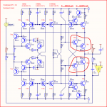
Cascode Current Mirror With Super Beta Helper


Attachments
-
Active Cascode Current Mirror.pdf528.6 KB · Views: 135
-
Active Cascode Topology.pdf1 MB · Views: 172
-
Analysis simulation and circuit implementation.pdf511.3 KB · Views: 128
-
Cascode current mirror circuit.pdf640 KB · Views: 139
-
Cascode Current Mirror With Super Beta Helper.pdf346.6 KB · Views: 122
-
M12-DRV.pdf43.3 KB · Views: 139
-
M12-OUT.pdf36.9 KB · Views: 139
-
Precision current mirror arrays.pdf1,023.1 KB · Views: 159
As I see, you have collected various complex schemes that you show here, but you yourself do not understand anything from them, and therefore there is no comment why you show them.
Accurate current mirrors are important for some applications but mostly for DC
But in Audio, this is not important at all!
It is much more important that the current mirror has high output impedance and low capacitance.
Because THD depends on non-linear capacitances. (varicaps)
All the schemes shown by you were made by people who do not understand electronics, but simply collected good ideas in one place, but in the worst way, which is why the result is mediocre.
Attachments
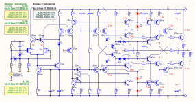
It looks optimistic, but perhaps I do not agree that this is a further optimization, rather it is a retrospective, because. I see solutions in the circuits that were relevant for electronics developers 20-30 years ago, but not now .... and if you look at it, it looks somewhat one-sided, i.e. only minimizing the error of the operating modes of the electronics cascades, this is beyond the sensitivity of an audiophile's hearing.Further Optimization of Circuit
The correlation of the subjective perception of sound and the topological decision of the audio amplifier requires a different approach, especially amplifier correction.
once in an interview, Den himself admitted that the latest developments Krell are inferior in terms of sound comfort to simpler audioamplifiers ...Then why does Krell use high-precision current mirror?
As I see it, you have put together various complex schemes that you show here, but you yourself do not understand any of them, and therefore there is no comment as to why you show them.
Accurate current mirrors are important for some applications, but mostly for DC
But in audio this is not important at all!
It is much more important that this mirror has high output impedance and low capacitance.
Because THD depends on non-linear capacitances. (varicaps)
All the schematics shown by you are made by people who do not understand electronics, but just collect good ideas in one place, but in the worst way, so the result is mediocre.
Well, the fact that someone uses them where there is no use for them, simply shows that he is not aware of where it is useful, and where it can be done with a simpler schematic solution.
If he understood he would just check all these circuits what PSRR they have.
Attachments
Last edited:
Hi Fi audio does not just stay on the simulation. If you can make good audio only by simulation, then the simulation software company will be the best audio company?


Attachments
I feel like I'm in a bar with several drunk guys, everyone hits each other but we don't even know why anymore, I'm going to go get some fresh air.
Here we say "opinions are like the a.s.s.h.o.l.e, everyone has one"
Here we say "opinions are like the a.s.s.h.o.l.e, everyone has one"
levinson mark,
From what you did not write, I understand that you yourself do not understand anything about electronics.
All the schemes you have shown here are examples of bad use of good ideas with mediocre results.
Uploading hundreds of different foreign schemes that everyone has seen without any comment or at least parameters of these schemes is pointless.
Yes, in audio as in everything else there is a lot of PR and marketing.
All manufacturers are looking for ignorant people to take their money.
But here we are talking about amateurs who want to do something for themselves.
So we should avoid marketing and psychiatry.
Yes, people without knowledge on the subject can only rely on their ears, but the problems start when they turn off their brains.
And I don't have a medical education, so I don't argue when it comes to subjective evaluations (likes)
Here is such an I/V converter using the same TIS output circuit, but with 10 times better parameters than the one shown by you.
The input resistance of your I/V is 8.75 ohms and is non-linear, mine is 1 ohm and is a linear active resistance.
Yours uses current mirrors which still distort, although not much.
That's why I don't use current mirrors in my I/V
So if you can't show something new and meaningful, don't clutter the topic with banal nonsense.
Attachments
- Home
- Amplifiers
- Solid State
- Apex A40 fundamental improvement. (Sandy)