No one is stopping anyone from liking something and using it.
Both the dung beetles and I like steaks, but the dung beetles just prefer them once eaten.
Different organisms different tastes.
That's exactly why it's silly to compare tastes.
However, a little common sense is needed to understand this.
Create your own fan clubs of various delightfully perverse schemes and deify them at will.
Here, in this topic raised by me, they are talking about completely different things, how to make things good from an engineering point of view, with better parameters.
An equal engineering challenge is how to make something maximally good and achieve it with a minimal amount of parts.
For me, a 1-2% improvement in some parameter but with 25-50% more parts is not an achievement, it's just plain stupid.
The schemes you have shown here fall into this category.
And there are those in which the complicating factor gives a significantly worse result than if it were not there.
But these things naturally cannot be understood by non-specialists who do not understand even the zaokan of Om.
If we are going to make a competition on stupid schematic solutions, I can upload here even more stupid ones than the ones you show.
circuits of the level of "transistor acrobatics".The schemes you have shown here fall into this category.
one Miller correction capacitor nullifies the "grape clusters of the transistor vineyard" ...
none of what was shown impressed me at all, and I want to ask: why is all this? where is the sound quality?
At first I thought it was a computer 1976 года...this is fundaMental thread .. 😀
Attachments
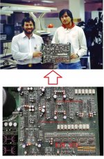
Yes, in 1976 there were still smart people in the west who knew about electronics.
And from which we learned.
Bob Pease, Jiri Dostal, Bob Widlar, ...... !!
Today there are no people who even understand what they wrote!
And from which we learned.
Bob Pease, Jiri Dostal, Bob Widlar, ...... !!
Today there are no people who even understand what they wrote!
https://sound.zp.ua/brends/krell/cast.htm


Кабели межблочные CAST (Current Audio Signal Transmission) - это запатентованная технология

Current mirror research.
levinson mark,
When people lacking analytical thinking try to copy circuit solutions from integrated circuits, the result is usually deplorable.
More parts for worse results.
The problem is that the public accepts such people as specialists.
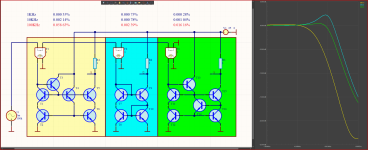
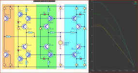
The current mirror on the right (green) is even more accurate when it comes to DC and has a much wider bandwidth.
But when it comes to THD and bandwidth, nothing beats the Wilson Current Mirror.
And with 50% fewer transistors.
And before a person engages in something stupider, he just needs to spend 10 minutes and see the difference in at least one simulator.
But of course this is not within the power of people who do not have some basic minimum of technical knowledge.
2-2.5 times the high THD of the low frequencies will be easily reduced by the feedback because it is deeper there.
But already at 10KHz things are already reversed and at 100KHz the difference is 24 times in favor of the Wilson Current Mirror
levinson mark,
When people lacking analytical thinking try to copy circuit solutions from integrated circuits, the result is usually deplorable.
More parts for worse results.
The problem is that the public accepts such people as specialists.
The current mirror on the right (green) is even more accurate when it comes to DC and has a much wider bandwidth.
But when it comes to THD and bandwidth, nothing beats the Wilson Current Mirror.
And with 50% fewer transistors.
And before a person engages in something stupider, he just needs to spend 10 minutes and see the difference in at least one simulator.
But of course this is not within the power of people who do not have some basic minimum of technical knowledge.
2-2.5 times the high THD of the low frequencies will be easily reduced by the feedback because it is deeper there.
But already at 10KHz things are already reversed and at 100KHz the difference is 24 times in favor of the Wilson Current Mirror
Attachments
Last edited:
Yes, music is not simulated, it is listened to and the impressions of it are shared with people with the same taste.
The problem is with those people who listen to electric mirrors instead of music.
Impressions of listening to electric mirrors should be shared not in the forums, but with a personal psychiatrist.
All these schemes you upload, what advantages do they have??
Do they make big but nice distortions??
I have nothing against people who like big distortions.
But here the topic is not about pleasant distortions, and different people have different tastes.
As they like different genres of music, they like different distortions.
Start a new topic for large distortions, and there upload the schemes that make pleasant distortions for you, and look for like-minded people.
This topic is for people who like unaltered music.
That is, whatever we have applied to the input of the amplifier, to pass through it with the maximum possible accuracy, minimum THD.
Levinson Mark,
It's best to find a hobby that doesn't require thinking.
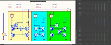
It's a little better without the RC but it's still infinitely worse.
Wilson's 28% gain is at a frequency that the output repeaters would cut, so it's not a problem at all.
And there, at the output of the VAS, there is usually a capacity for frequency correction.
But how can a person with superficial knowledge and devoid of logical thinking understand these things.
It's best to find a hobby that doesn't require thinking.
It's a little better without the RC but it's still infinitely worse.
Wilson's 28% gain is at a frequency that the output repeaters would cut, so it's not a problem at all.
And there, at the output of the VAS, there is usually a capacity for frequency correction.
But how can a person with superficial knowledge and devoid of logical thinking understand these things.
Attachments

Last edited:
Mark Levinson,
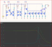
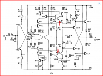
If they gave out Oscars for how to achieve the maximum bad result with the maximum number of transistors, you'd win it.
The yellow is your VAS ideas, is it worth 6 elements more, compared to the simplest common base scheme, for the minimal difference below 1KHz.
The graph shows the output impedance in Db relative to 1 ohm
145.6dB = 19MΩ
169.46dB = 297MΩ
196.77dB = 6.89GΩ
Attachments
Last edited:
Sorry, you are not simulating the patented current mirror of Krell。Krell did not publish the complete circuit of its patented current mirror.


That's a good idea. Unfortunately, the publishing house did not invite you to be the editor in chief.


- Home
- Amplifiers
- Solid State
- Apex A40 fundamental improvement. (Sandy)