Sometime is realy necesary to translate your English into proper electronic one, like restriction -> saturation in previous post and so on.
Realy is not easy for me to follow your discussion, rather pity, as looks very intersting.
Most of members here use LTspice and better understand it than spice you are using here. Those diagrams are hard for me to follow.
Realy is not easy for me to follow your discussion, rather pity, as looks very intersting.
Most of members here use LTspice and better understand it than spice you are using here. Those diagrams are hard for me to follow.
My knowledge of English is like petr_2009's knowledge of electronics. 😉
To be honest, I'm a moron in this area. 😢
I translate Bulgarian to English and then back to Bulgarian.
And I rarely understand what I wrote.
Next is a remaking of the primary text, so that something meaningful is obtained when the primary text is reversed.
Working with LTspice is downright masochistic compared to Altium.
And precisely Altium graphics are significantly more understandable, because you can make them in any combination and format.

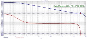
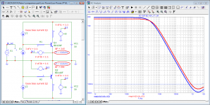
yes, I saw it, I also noticed that the slopes of the frequency response near the unity gain frequency correspond to the necessary ones, for this a high point is actually created for correction due to an additional feedback circuit from the output stage. This is probably original, because it takes into account the peculiarity of the implementation of the output stage, but to what extent - you need to look and try practically ...You can try this type of compensation. https://www.diyaudio.com/community/threads/oitpc-output-inclusive-tpc-not-tmc.317335/
yes, it doesn't translate well.You call it correction, probably Google translation?
missed the second correction, but it will not save the situation. Amplifier not working!
Use, Sandy, normal models of transistors.
Then there will be fewer jambs.
And on ideal transistors, any circuit will work for any sofa designer
Use, Sandy, normal models of transistors.
Then there will be fewer jambs.
And on ideal transistors, any circuit will work for any sofa designer
Attachments
Well, if you had at least a little understanding of electronics, you would be able to adjust the frequency correction according to your transistor models.
Instead, a Probe1 split the high-inductance, high-capacitance feedback to the generator.
And then see the true frequency response of the amplifier without feedback.
Idiot experimental setups lead to idiotic results.
Probe1 should not be between the output of the amplifier and the load.
It should be in series only on the feedback R7C1
Last edited:
I don't want to argue what is better, but LTspice is just very simple, at least for me.Working with LTspice is downright masochistic compared to Altium.
And precisely Altium graphics are significantly more understandable, because you can make them in any combination and format.
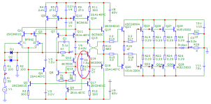
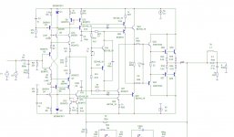
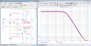
A characteristic feature of Apex A40 is the use of compensation of h22b and Сcb of transistors in VAS.
This allows a further large reduction of THD occurring in the output of the VAS.
In my version, such compensation is also used, but it is done by a different method.
Here I show you the difference VAS1 is compensated and therefore has an additional gain of 120 times.
VAS2 is without such compensation the bases of T19/T20 are connected to the zener diodes.
Attachments
Sandy and Hennady, you can prove to each other for a long time which of you is right.Probe1 should not be between the output of the amplifier and the load.
It should be in series only on the feedback R7C1
Use corrected models, not those in simulators.
Sandy, regarding loop gain measurements using the old-fashioned method.
Even the old-fashioned method does not save the day! As you can see, the result is the same.
Attachments


Sandy and Hennady, you can prove to each other for a long time which of you is right.
Use corrected models, not those in simulators.
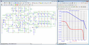
There is no dispute. When using models from Cordell in my version of the mod, it is only necessary to exclude the 22pF capacitance that shunts the 1 kΩ input resistor. Everything else remains the same, at least for me...and diodes D3D4 must be transferred to the collectors of the transistors of the voltage amplifier.
Attachments
Last edited:
The fact that you don't know and can't do the frequency correction according to your models is your problem!!
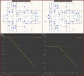
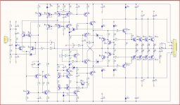
Here is the same circuit with other BF420/BF423 transistors (Audio-PA-4xMJE1532 sim)
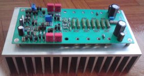
Here is the working one and not one for simulation (PA-4xMJE1532)
And whether it works can be seen by doing it live.
And if it works live and in the simulator of a prodigy it doesn't work, the problem is with the prodigy.
Naturally with MJE15032 and 75V power supply it cannot give 450W because it will overheat.
Live it should run at 8 ohms when powered.
But there is such a simulation to see the capabilities of the scheme itself.
Here is the same circuit with other BF420/BF423 transistors (Audio-PA-4xMJE1532 sim)
Here is the working one and not one for simulation (PA-4xMJE1532)
And whether it works can be seen by doing it live.
And if it works live and in the simulator of a prodigy it doesn't work, the problem is with the prodigy.
Naturally with MJE15032 and 75V power supply it cannot give 450W because it will overheat.
Live it should run at 8 ohms when powered.
But there is such a simulation to see the capabilities of the scheme itself.
Attachments
Here is the BD139/BD140 model provided by the company that manufactures it.
One time I was stupid and took transistor models from this forum.
*****************************************************************************
. МОДЕЛ BD139C NPN (
. МОДЕЛ BD140C PNP (
One time I was stupid and took transistor models from this forum.
*****************************************************************************
. МОДЕЛ BD139C NPN (
- IS=150e-15 BF=260 VAF=99 IKF=1.2 ISE=70e-15 NE=1.2 NF=1.0
- RB=5 RC=0.01 RE=0.08 CJE=293e-12 MJE=0.33 VJE=0.67 CJC=49e-12
- MJC=0,39 VJC=0,52 FC=0,5 TF=585e-12 XTF=10000 VTF=35 ITF=20
- TR=10e-9 BR=78 IKR=0.14 EG=1.21 XTB=1.14 XTI=3 NC=1.45
- ISC=19e-12 NR=1.0 VAR=7.5 IRB=0.03 RBM=0.001 XCJC=0.53 )
. МОДЕЛ BD140C PNP (
- IS=120e-15 BF=113 VAF=140 IKF=1,5 ISE=1000e-15 NE=1,5 NF=1 RB=5
- RC=0,01 RE=0,1 CJE=220e-12 MJE=0,35 VJE=0,7 CJC=68e-12 MJC=0,35
- VJC=0,6 XCJC=0,5 FC=0,5 TF=320e-12 XTF=10000 VTF=35 ITF=20
- TR=100e-9 BR=25 IKR=0,1 EG=1,2 XTB=1,5 XTI=3 NC=1,4 ISC=7e-12
- NR=1.0 VAR=8 IRB=0.01 RBM=0.01 )
I understand that mainly amateurs write here and it is normal that they do not have a great knowledge of electronics.
They of course rely on the simulator to think for them.
No simulator can give you a 100% match with the live amp.
Live frequency corrections are always different by up to 50-100% on large capacities typically.
The simulator is a good tool to compare different circuit solutions.
In such a comparison, the models for both schemes are the same.
So the differences between the two schemes in the simulator will not be due to model differences.
Simulators cannot think, but unfortunately sometimes they are smarter than those who use them. 😉 😉
This is exactly the same to Cordell models used by most here with LTspice.Here is the BD139/BD140 model provided by the company that manufactures it.
One time I was stupid and took transistor models from this forum.
*****************************************************************************
. МОДЕЛ BD139C NPN (
*****************************************************************************
- IS=150e-15 BF=260 VAF=99 IKF=1.2 ISE=70e-15 NE=1.2 NF=1.0
- RB=5 RC=0.01 RE=0.08 CJE=293e-12 MJE=0.33 VJE=0.67 CJC=49e-12
- MJC=0,39 VJC=0,52 FC=0,5 TF=585e-12 XTF=10000 VTF=35 ITF=20
- TR=10e-9 BR=78 IKR=0.14 EG=1.21 XTB=1.14 XTI=3 NC=1.45
- ISC=19e-12 NR=1.0 VAR=7.5 IRB=0.03 RBM=0.001 XCJC=0.53 )
. МОДЕЛ BD140C PNP (
*****************************************************************************
- IS=120e-15 BF=113 VAF=140 IKF=1,5 ISE=1000e-15 NE=1,5 NF=1 RB=5
- RC=0,01 RE=0,1 CJE=220e-12 MJE=0,35 VJE=0,7 CJC=68e-12 MJC=0,35
- VJC=0,6 XCJC=0,5 FC=0,5 TF=320e-12 XTF=10000 VTF=35 ITF=20
- TR=100e-9 BR=25 IKR=0,1 EG=1,2 XTB=1,5 XTI=3 NC=1,4 ISC=7e-12
- NR=1.0 VAR=8 IRB=0.01 RBM=0.01 )
It's normal, petr_2009 is fighting windmills again. 🤣
I once had a problem with models taken from this forum.
The simulation of the growth rate came out 5 times greater than the one calculated on paper.
And I immediately checked the models of the transistors in the VAS, they turned out to have no capacities at all.
That's why I no longer use models taken from audio constructors announced here as great.
BD139/140 aew not suitable for VAS.It's normal, petr_2009 is fighting windmills again. 🤣
I once had a problem with models taken from this forum.
The simulation of the growth rate came out 5 times greater than the one calculated on paper.
And I immediately checked the models of the transistors in the VAS, they turned out to have no capacities at all.
That's why I no longer use models taken from audio constructors announced here as great.
Sandi, show the manufacturer's document from which you took these models with the "C" index. You don't even know that these are Bob Cordell models.Here is the BD139/BD140 model provided by the company that manufactures it.
One time I was stupid and took transistor models from this forum.
*****************************************************************************
. МОДЕЛ BD139C NPN (
. МОДЕЛ BD140C PNP (
BD136-BD140
I can't remember where I got all the models from, and there are >1000 of them in my computer...!!!
But most of them have been tested and give satisfactory results.
I can't remember where I got all the models from, and there are >1000 of them in my computer...!!!
But most of them have been tested and give satisfactory results.
Attachments
Hmmm, one who gives no respect deserves no better. 🙁... And I'm not using Cordell's made-up models.
I use the latest models from the manufacturers of the element.
*****************************************************************************
* BD135/137/139 NPN EPITAXIAL SILICON TRANSISTOR 2017
*------------------------------------------------------
.MODEL BD135_137_139 NPN (
*-------------------------------------------------------
* BD136/138/140 PNP EPITAXIAL SILICON TRANSISTOR 2017
*------------------------------------------------------
.MODEL BD136_BD138_BD140 PNP (
* BD135/137/139 NPN EPITAXIAL SILICON TRANSISTOR 2017
*------------------------------------------------------
- MEDIUM POWER LINEAR AND SWITCHING APPLICATIONS
- Based on BD135-16
- BVcbo: BD135 45V / BD137 60V / BD139 80V
- BVceo: BD135 45V / BD137 60V / BD139 80V
- BVebo: 5V
- Complement to BD136, BD138 and BD140 respectively
.MODEL BD135_137_139 NPN (
- CJC =4.8831E-11
- CJE =2.92702E-10
- IS =2.3985E-13
- BF =244.9
- NF =1.0
- BR =78.11
- NR =1.007
- ISE =1.0471E-14
- NE =1.2
- ISC =1.9314E-11
- NC =1.45
- VAF =98.5
- VAR =7.46
- IKF =1.1863
- IKR =0.1445
- RB =2.14
- RBM =0.001
- IRB =0.031
- RE =0.0832
- RC =0.01
- VJE =0.67412
- MJE =0.3300
- FC =0.5
- VJC =0.5258
- MJC =0.3928
- XCJC =0.5287
- XTB =1.1398
- EG =1.2105
- XTI =3.0 )
*-------------------------------------------------------
- FAIRCHILD CASE: TO-126 PID:BD135-16
- 2000-03-20 CREATION
* BD136/138/140 PNP EPITAXIAL SILICON TRANSISTOR 2017
*------------------------------------------------------
- MEDIUM POWER LINEAR AND SWITCHING APPLICATIONS
- Based on BD140-16
- BVcbo: BD135 -45V / BD137 -60V / BD139 -80V
- BVceo: BD135 -45V / BD137 -60V / BD139 -80V
- BVebo: -5V
- Complement to BD135, BD137 and BD139 respectively
.MODEL BD136_BD138_BD140 PNP (
- CJC =6.8291E-11
- CJE =2.1982E-10
- IS =2.9537E-13
- BF =201.4
- NF =1.0
- BR =23.765
- NR =1.021
- ISE =1.8002E-13
- NE =1.5
- ISC =7.0433E-12
- NC =1.38
- VAF =137.0
- VAR =8.41
- IKF =1.0993
- IKR =0.10
- RB =1.98
- RBM =0.01
- IRB =0.011
- RE =0.1109
- RC =0.01
- VJE =0.7211
- MJE =0.3685
- FC =0.5
- VJC =0.5499
- MJC =0.3668
- XCJC =0.5287
- XTB =1.4883
- EG =1.2343
- XTI =3.0 )
- Home
- Amplifiers
- Solid State
- Apex A40 fundamental improvement. (Sandy)