My unswer was reaction on your use of the ordinary miller compesation cap and not liking two pole compensation.This peak is a function of the phase margin, and does not need to be compensated.
30-45 degrees is perfectly acceptable, and with such a phase margin, there will be deeper feedback, and hence lower THD.
But then the amplifier becomes more sensitive to capacitive loads if measures are not taken for this with an RL circuit at its output.
The input RC circuit is typically 1k/100pF (1.6MHz) to prevent radio interference from entering the input.
In my amp I am using LR at the amp output and lowpass filter on the input but with lover value resitor and higher value capacitor.

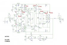
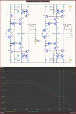
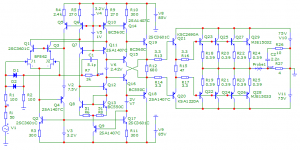
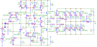
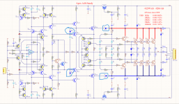
modified Sandy's circuit for +/-50 volt supply voltage, 200 watt output power into 4 ohm load.
what was done?
1. increased current to 5.6mA through zener diodes
2. Increased input stage gain from -3dB to 12dB
3. Gain is reduced to 26dB, because supply voltage only +/-50 volts
4. applied progressive correction at the input of the amplifier and increased the current through the main stage of the voltage amplifier
5. Malcolm's scheme was used to improve thermal stabilization
6. To stabilize the operating point at the output, a servo circuit on a dual op-amp was used.
Distortion does not exceed 0.001% (1kHz) with a short spectrum at maximum output power.
and of course, it cannot boast of hundreds of volts of slew rate and a minimum delay group, but everything is stable, stable and, judging by the simulation data, it is quite suitable for repetition even in amateur conditions.
Attachments
Why is your gain 10 between input and VAS ??
Why is your VAS current 27mA?
Gain 10 (R10/R16) makes 10 times the low frequency.
And it already takes 10 times as long as a large capacitor (C5/C6)
Using BD139/140 for 27mA current is a huge folly because of 10-20 times their large Ckb capacities.
The biggest distortions come from VAS and from the capacities Ckb they are varicaps !!!!
What is the point of Q19/Q22 being BD139/140.
There's more nonsense, but let's discuss those first.
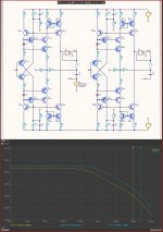
Even if a person doesn't understand much about electronics and has never calculated anything on paper, he can at least compare 2 things easily in the simulator.
Here is the difference between the BD139/2N5551 used in the VAS
Here is the difference between the BD139/2N5551 used in the VAS
Attachments
Last edited:
are you sure what you write?Even if a person doesn't understand much about electronics and has never calculated anything on paper, he can at least compare 2 things easily in the simulator.
can you calculate on a piece of paper the power that 2N5551 needs to dissipate?Here is the difference between the BD139/2N5551 used in the VAS
and write here the maximum power dissipation 2N5551 Pкmax(т)!!!
Attachments
It was not by chance that I asked you what the current 27mA in VAS is for??
As your next stage, Q20/Q21 operates with a current of 3.6mA
I just wanted to show how the transistor capacitances affect.
There are enough transistors in the TO126 package for a current of 50-100mA with little Ckb.
But if we reduce the VAS current to 2.5-3mA, 2N5551/2N5401 become perfect for this place, or similar for current up to 100mA and with small powers.
You see I use KSA1381/KSC3503 precisely because of Pk although I use low current but voltage is high.
For your lower voltage there are even faster 2SA1538/2SC3953 Ft=400MHz
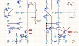
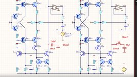
So are you happier with a TO126 case
Last picture VAS 2.9mA current!!
What is the benefit of high current ???
Last picture VAS 2.9mA current!!
What is the benefit of high current ???
Attachments
Last edited:
It was not by chance that I asked you what the current 27mA in VAS is for??
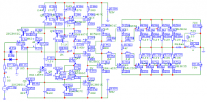
on the one hand, I received a linear gain of the input transistor according to the scheme with a common base Ku8 Ku10 equal to 12dB, on the other hand, the current was increased 10 times for the main driver transistor, which will easily pump the correction capacitors C5C6 and its parameters will not depend on changes in the differential resistance of the multiplier Malcolm on signal strength and temperature.
Оf course, the power dissipation increased and the 2N5551 / 5401 transistors were no longer suitable for the maximum power dissipation parameter.
Q19/Q22 also replaced by medium power transistors, because the current increased by 1.5 times.
this will require high-quality PCB layout.For your lower voltage there are even faster 2SA1538/2SC3953 Ft=400MHz
P.S. Perhaps later it will be possible to increase the order of correction in order to raise the pole up in frequency.
Attachments
To answer this question correctly, you need to add a correction capacitor in your model, which you don't show for some reason.So are you happier with a TO126 case
Last picture VAS 2.9mA current!!
What is the benefit of high current ???
Attachments
What's the point of doubling the zener diode current if the result is 2x worse PSRR ???
yes, it is better to increase the 15k resistors to 1 Mohm.
ok.
However, the results are the exact opposite of your reasoning!!
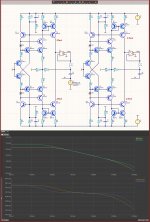
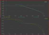
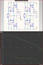
As we use a current mirror (Ku=1) and not a current amplifier with Ku=10.
We get 15.4dB of apparent gain for the low frequencies almost the same for 100KHz-1MHz and higher above 10MHz
And why this is so is simple.
At 10 times higher current the transistor has 10 times lower h22e. And on the powerful transistor there is also a larger Ckb which is the main load for the high frequencies.
In one place we amplify 10 times, but in another we reduce it more than 10 times and the result is the opposite.
Attachments
Sandy, what's wrong with the model again that it's inoperable? For good, it would not hurt to indicate at least a prototype.
To broaden your horizons:
Back in 1960, Otala drew attention to the distortion caused by turning (voltage deviation from a pure sinusoidal voltage as a result of changes in both the amplitude of the signal and its frequency), this type of distortion is called SID.
Later in the article "An overview of SID and TIM" Walter Jung writes the following:
"Thus, it should be appreciated (in a qualitative sense) that SID (or TIM) is a distortion which is level sensitive in terms of both amplitude and frequency (since both affect SS)."
But for you, there are no other types of distortion other than THD
Sandy, there is a joke about the distortions that you don’t have in amplifiers.
At the bus stop is a young girl in a black skirt. The young man noticed a white thread on the back of her skirt, approached the girl and embarrassed (didder), did not know how to say:
girl, you have ..., you have a white thread on ...
Where ?, the girl says and turns around, on her ***, or what?
Girl, there is no such word!
There is no word, the girl answers, but there is an ***
Attachments
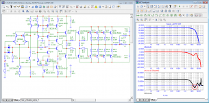
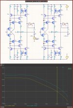
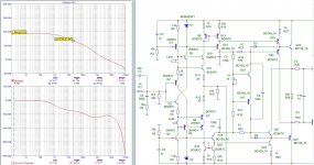
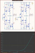
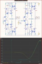
First we need to see things without frequency correction.To answer this question correctly, you need to add a correction capacitor in your model, which you don't show for some reason.
It is clear that the amplifier that has a wider frequency band without correction will be better even after the correction.
240pF/24pF
Same Ft in practice but worse above 1MHz.
And here the phase shift of the next step will also be added.
We can see that the amplification for low frequencies is much worse at the high current of VAS
And there is no benefit from this large current, even at high frequencies the phase is worse.
Attachments
What's the point of doubling the zener diode current if the result is 2x worse PSRR ???
What will happen in the clip with driver transistors when there is not enough current for the zener diode? In fact, because of this, I put resistors to double the current ...
We can see that the amplification for low frequencies is much worse at the high current of VAS
And there is no benefit from this large current, even at high frequencies the phase is worse.
However, the linearity of the gain with such a low-current driver is higher. I'll try to re-correct for a low-power driver, but the current increased due to the poor quality of the output stage control due to the weak driver current.
There is no frequency correction in VAS!!Sandy, what's wrong with the model again that it's inoperable? For good, it would not hurt to indicate at least a prototype.
To broaden your horizons:
Back in 1960, Otala drew attention to the distortion caused by turning (voltage deviation from a pure sinusoidal voltage as a result of changes in both the amplitude of the signal and its frequency), this type of distortion is called SID.
Later in the article "An overview of SID and TIM" Walter Jung writes the following:
"Thus, it should be appreciated (in a qualitative sense) that SID (or TIM) is a distortion which is level sensitive in terms of both amplitude and frequency (since both affect SS)."
But for you, there are no other types of distortion other than THD
Sandy, there is a joke about the distortions that you don’t have in amplifiers.
At the bus stop is a young girl in a black skirt. The young man noticed a white thread on the back of her skirt, approached the girl and embarrassed (didder), did not know how to say:
girl, you have ..., you have a white thread on ...
Where ?, the girl says and turns around, on her ***, or what?
Girl, there is no such word!
There is no word, the girl answers, but there is an ***
Otala and company are technically illiterate people.
Dot Quixotes who invent "windmills" to fight with.
I have already explained that nowhere in the amplifier is anything delayed as it is delayed in a delay line.
And therefore, the phase shift cannot be compensated with a delay line delay.
Transistors have capacitances and impedances that determine Ft and phase delays (RC circuits).
Smart people work with phase angles and frequency bands.
Masochists devoid of logical thinking express a phaozive angle with time lag.
It's true in theory, but it's inconvenient as hell in practice.
And it leads to the creation of "windmills" in some Don Quixote heads, struck by schizophrenia.
A packet of several 10KHz sines does not contain only 10KHz.
At the beginning and end there are also all harmonics n*10KHz (20-200000...KHz)
Naturally, an amplifier with a frequency band of 1MHz will not reproduce all of them.
Yes these are linear distortions (bandwidth limited)
An amplifier with a bandwidth of 100KHz has 100 times more linear distortion than one with a bandwidth of 10MHz.
But what if we don't feed it more than 20-100KHz
Smart people just measure the bandwidth of the amplifiers.
The Don Quixotes make stupid experimental setups, subtract the output signal from the input signal and see as a difference a signal formed by the high harmonics of those 10KHz because the amplifier has cut it.
And they think that these are some kind of distortions.
But go explain to a schizophrenic that what he sees exists only in his head.
It's a daunting task.
I showed you how to do it right.
With an RC circuit we limit the spectrum of the sine packet to about 100KHz
And for delay compensation (phase shift) we use an RC circuit and not a delay line.
And oh wonder, these imaginary distortions disappear.
You never understood the difference between an RC circuit and a delay line.
But for a prodigy like you, that's no surprise.
I explain as for prodigies and lastly!
RC circuit:
As the frequency increases, the amplitude decreases.
As the frequency increases, the phase angle becomes close to 90 and the time accordingly becomes shorter.
In other words, the higher the frequency, the faster it passes through the RC circuit, but the amplitude also decreases.
The delay line works just the other way around.
All frequencies are equally delayed!!!!
And the amplitude of the output is the same as that of the input.
You can try this type of compensation. https://www.diyaudio.com/community/threads/oitpc-output-inclusive-tpc-not-tmc.317335/P.S. Perhaps later it will be possible to increase the order of correction in order to raise the pole up in frequency.
You call it correction, probably Google translation?
Which gain linearity is higher and how did you know that?However, the linearity of the gain with such a low-current driver is higher. I'll try to re-correct for a low-power driver, but the current increased due to the poor quality of the output stage control due to the weak driver current.
The transistors in the VAS should never go into restriction.
This is solved in another way, noting the diode scheme.
R18/R19 are not there just for offset adjustment.
They are there to keep T13/T14 from clogging up under restriction.
A minimum current of at least 0.5mA always remains in the inactive arm
This is how you get out of the limit quickly.
And this does not allow them to change the voltage determining the quiescent current (U on C8) under limitation.
In your scheme, when the current through the transistors is limited, this voltage will become 0A
Here, however, even if T16 is blocked, T15 at 0.5mA remains unblocked and keeps the voltage of C8 from changing radically.
Also, C8 should never be large (electrolyte 100uF) as audio designers usually do, so that this voltage after the limit quickly returns to the required value.
You have to think about mongo things at the same time and their interrelationship.
Attachments
- Home
- Amplifiers
- Solid State
- Apex A40 fundamental improvement. (Sandy)