The operation of the amplifier is normalized for a certain range of load impedance. And now you can pick up a calculator yourself and calculate what the impedance of an 8uF capacitor at a frequency of 20 kHz will be. The simulator is good, but it does not replace brains.Sandy, feel the difference between the operation of the amplifier for active and reactive load

The operation of the amplifier is normalized for a certain range of load impedance. And now you can pick up a calculator yourself and calculate what the impedance of an 8uF capacitor at a frequency of 20 kHz will be. The simulator is good, but it does not replace brains.
fagos, even a calculator does not replace brains, let alone a simulator.
Before trolling, I would calculate (from the height of your education) what the peak current will be through the load impedance at an output voltage of 4 V (peak).
POWER AMPLIFIERS AND REAL-WORLD
SPEAKER IMPEDANCES
DRIVE REQUIREMENTS AND AMPLIFIER SELECTION CRITERIA
Mr. Manuel Huber,
President, FM Acoustics
Switzerland
Impedance, Damping and Load
«The lower the output impedance of the amplifier, the less negative influence the Back-EMF can have on the amplifier's circuit)'. Remember that the output impedance consists of amplifier and cable/connector! It is impedance of the entire interface that defines the damping of the diaphragm. In this criteria tube amplifiers fail to deliver accuracy (amplifiers having an output transformer can never provide optimal damping resulting in a corresponding mushy and ill-defined bass reproduction).
For a power amplifier the combination of the above-mentioned phenomena results in a very complex and continuously varying load that is changing dynamically with the frequency and the level of the music signal! Traditional design theory indicates that an amplifier output current capability in the region of 5 to 15A is sufficient, but in actual use peak current requirements of several hundred A are required when driving demanding speakers! It is not unusual to find that amplifiers that are specified for continuous 2 Ohms operation are failing to drive speakers with a nominal impedance of 4 Ohms without noticeable compression, signal damping, limiting or instability effects. At some frequencies some speakers (e.g. electrostatics) however can present a dynamic impedance roughly comparable to a 0.5 Ohms resistance! From this it becomes quite clear that most speaker cables are truly a weak link in audiophile systems.»
Empty blah-blah-blah with an attempt to make me do the calculations for you. And where is your argument? In fact, your excerpt does not show anything concrete, except for the opinion of a person without certain clear calculations and examples. I can cite a lot of such vague ones, but it will not become the truth. Let's load the amplifier on a rusty nail then, since everything is so bad in the real world. At the same time, we will make it work as a welding source if necessary. Everything should have clear boundaries of acceptable use, right?fagos, even a calculator does not replace brains, let alone a simulator.
Before trolling, I would calculate (from the height of your education) what the peak current will be through the load impedance at an output voltage of 4 V (peak).
P.S. I will ask you not to touch my education with your hands. You do not have a specialized education at all and this does not prevent you from making a smart look and teaching everyone in the tone of a guru. Maybe this is the problem of your misunderstanding?
Let's load the amplifier on a rusty nail then, since everything is so bad in the real world. At the same time, we will make it work as a welding source if necessary. Everything should have clear boundaries of acceptable use, right?
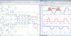
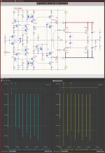
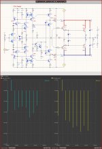
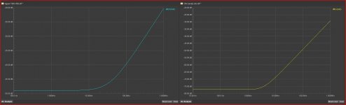
Okay, let's load the amplifiers on the "rusty nail" in your terms and see if the amplifiers can handle the load as welding source.
As we see:
In one, the peak collector current reaches 1 A, or the short-term power dissipation on the transistor is 70 watts. And oh horror - the first period is heavily distorted (what Graham Maynard warned about).
At the second amplifier, the peak current reaches 4 A and the short-term dissipated on transistor power reaches as much as 80 watts.
Even calculations on a piece of paper in a cell did not help you (as Sandy says - there was not enough intelligence to figure it out).
Attachments
We know that thinking is not your thing.
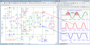
The first scheme has 4 final transistors, so the output current is 4 times larger, and is 4A!!
I also made a frequency correction of the amplifier so that it can work with a capacitive load of 8uF.
So make fair comparisons. Either both circuits with no inductance in the output or both with inductance in the output.
To talk to you, a person needs a medical education.
Not to say that such a load is unreal.
What is the inductance of the cable to the speaker
I'm interested in building similar Ageev amp like proposed by Mr Petrov, but with different OS (vertical mosfets).Pert 2009 doesn't seem to know that in practice gate servo control with input single-ended Jfet is very far from the parameters that are obtained in the simulation.
And if he really listened in practice to those models that flood the forum, then the servo would have been implemented differently, but no, there is what it is ....
What's wrong with this servo? How should it be implemented?
Do you feel sorry for free time?I'm interested in building similar Ageev amp like proposed by Mr Petrov, but with different OS (vertical mosfets).
The theoretical blank like proposed by Mr Petrov will take a very long time to "finish"
high-quality servo blocks in a power amplifier are formed from an op-amp in an inverting connection ...What's wrong with this servo? How should it be implemented?
the use of a first-order filter with an op-amp in a non-inverting connection, and even in an input circuit with an open input, is "to chickens for laughter" ....you can see for yourself by soldering the amplifier as recommended by Petrov
Adeev's amplifier is an example of how amplifiers should not be made.
In the simulator, two identical transistors are exactly the same, but never in real life.
Mf,dor jds m,r'rkd
Therefore, the quiescent current of the input and output transistors of a real circuit is a big puzzle.
The selection of many identical pairs of transistors is required.
The current generator with the BSP149 also sets the maximum possible current through the terminal basе.
So the maximum output current which will depend on h21e
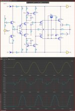
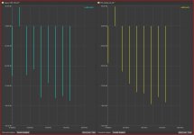
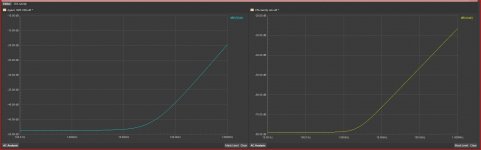
Here is an honest comparison of my amplifier and Adeev's, with the same +/-25V supply and the same 6 ohm and 8uF load at 20V output voltage at 20KHz
And also with equal gain Ku=17
You can see the deplorable result.
But that's what happens when people without the necessary technical knowledge struggle to deal with things they don't understand anything about.
In the simulator, two identical transistors are exactly the same, but never in real life.
Mf,dor jds m,r'rkd
Therefore, the quiescent current of the input and output transistors of a real circuit is a big puzzle.
The selection of many identical pairs of transistors is required.
The current generator with the BSP149 also sets the maximum possible current through the terminal basе.
So the maximum output current which will depend on h21e
Here is an honest comparison of my amplifier and Adeev's, with the same +/-25V supply and the same 6 ohm and 8uF load at 20V output voltage at 20KHz
And also with equal gain Ku=17
You can see the deplorable result.
But that's what happens when people without the necessary technical knowledge struggle to deal with things they don't understand anything about.
Attachments
Sandy, your amp is inoperable without inductance at the output with Cordell's normal transistor models. You seem to have decided to test the amplifiers as welding current sources for a "rusty nail" on the advice of the fagos. As they say: "С дуру можно и хрен сломать".
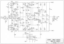
I was thinking about Ageev amp, but with different OS, something like in this picture (work in progress):

peter_2009,
That you are blind is not news to us.
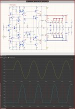
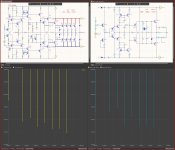
Well, the frequency correction here has been changed, it is not like the original scheme, just to be able to work without the output inductance of a capacitive load of 8uF.
And the simulation perfectly shows that it works perfectly even at 20Vmax in the output at 20KHz.
And look, your scheme does not work at all at such an output voltage and at such a frequency.
And I'm not using Cordell's made-up models.
I use the latest models from the manufacturers of the element.
That you are blind is not news to us.
Well, the frequency correction here has been changed, it is not like the original scheme, just to be able to work without the output inductance of a capacitive load of 8uF.
And the simulation perfectly shows that it works perfectly even at 20Vmax in the output at 20KHz.
And look, your scheme does not work at all at such an output voltage and at such a frequency.
And I'm not using Cordell's made-up models.
I use the latest models from the manufacturers of the element.
Excuse me, but this is just awful....I was thinking about Ageev amp, but with different OS, something like in this picture (work in progress):
I don't need to glue your fantastic idea to load the amplifier at 8uF. It was your idea, but you like to confuse people who don't read from the beginning and shift mistakes to others, as if by accident. Break what you want, but it's your responsibility and your Cabbage family plant.Sandy, your amp is inoperable without inductance at the output with Cordell's normal transistor models. You seem to have decided to test the amplifiers as welding current sources for a "rusty nail" on the advice of the fagos. As they say: "С дуру можно и хрен сломать".

I was thinking about Ageev amp, but with different OS, something like in this picture (work in progress):
View attachment 1106883
A similar scheme already exists in a worked out form. https://www.diyaudio.com/community/threads/200w-mosfet-cfa-amp.243481/post-6929696
But for those who do not understand - it's certainly terrible!🙂
p.s.
I look for likes and see: "the cuckoo praises the rooster for the fact that he praises the cuckoo"
Attachments
Last edited:
of course, here even an amateur will find 10 fundamental differences, and there are no stupid ideas here Petr 2009 ....But for those who do not understand - it's certainly terrible!🙂
p.s.
100W-CFA can't be compared to Adeev's crap at all.
Although it unnecessarily complicates the input part (current generators do not need a cascode), without any benefit.
MOS final transistors today when the final BJTs are already 30MHZ is a stupid decision.
Their steepness is 10 and more times lower than BJT. The difference between p/n channels is too big.
All this results in poor THD.
- Home
- Amplifiers
- Solid State
- Apex A40 fundamental improvement. (Sandy)