it looks like this diagram:Let's see how the Cortez test will pass, the winner of the "Radio 60" competition with a supply voltage of + -25 V.
As you can see, no problem!
Attachments
Damir, what is the current bias of this amplifier (100 CFA)?Is this enough loop gain at 20kHz?
All data you can find in the tread.Damir, what is the current bias of this amplifier (100 CFA)?
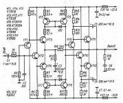
it looks like this diagram:
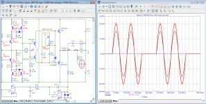
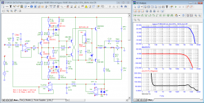
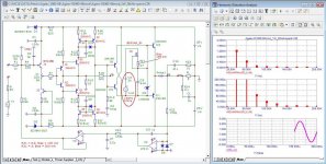
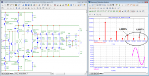
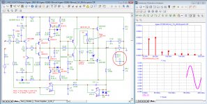
Today I would slightly modify the circuit to look like fig. 01
- The buffer at the input stabilizes the parameters, making them independent of the resistance of the signal source;
- The input stage is made by analogy as in the Cyrus-3i amplifier;
- The output stage is made according to the ideas of Dmitry Kireev (deemon). The parallel output stage with voltage boosts has been replaced with Darlington "twos".
- In general, the amplifier is made according to the DC amplifier circuit.
- To maintain zero output, a servo control circuit is applied.
- The amplifier does not need an output inductance for stable operation.
As a result of refinement, we have a Rail-to-Rail amplifier.
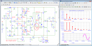
The spectrum of higher harmonics is short - in fact the 2nd and 3rd harmonics.
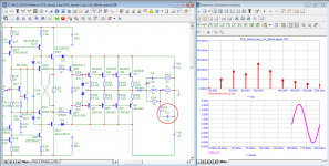
Switching and high-speed distortions are almost completely absent.
The quiescent current of the output transistors sets a stable current source on the field-effect transistor and can be set within 100...200 mA (according to the thermal resistance of the heat sinks).
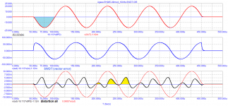
The group delay time of the signal does not exceed 50 ns and is constantly at least up to a frequency of 1 MHz, which guarantees low distortion in the time domain, including the absence of transient distortion at a frequency of 20 Hz.
Attachments
-
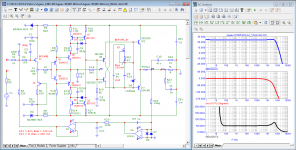 01_Ageev_R1985-08mod_Bode.png37.5 KB · Views: 161
 -
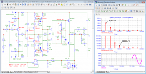 02_Ageev_R1985-08mod_1W_20kHz-spectr.png38.3 KB · Views: 153
 -
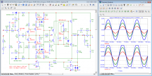
 03_Ageev_R1985-08mod_10kHz(+)-SWDT.png18.4 KB · Views: 121
 -
 03a_Ageev_R1985-08mod_10kHz(-)-SWDT.png18.1 KB · Views: 101
 -
 04_Ageev_R1985-08mod_10kHz-test_John_Curl.png35.9 KB · Views: 90
 -
 05_Ageev_R1985-08mod_20Hz-burst.png12.8 KB · Views: 114
 -
 06_Ageev_R1985-08mod_20kHz-clipping.png41.1 KB · Views: 165
petr_2009, is it possible to:
a) replace jfets with BJTs in the input buffer? or even better - with jfet op-amp (e.g. TL071) ?
b) use TL072 op-amp for the servo?
a) replace jfets with BJTs in the input buffer? or even better - with jfet op-amp (e.g. TL071) ?
b) use TL072 op-amp for the servo?
Last edited:
petr_2009, is it possible to:
a) replace jfets with BJTs in the input buffer? or even better - with jfet op-amp (e.g. TL071) ?
b) use TL072 op-amp for the servo?
It is desirable to use an amplifier with a low tPD as an OPA for the input buffer.
For servo control, any amplifier with field-effect transistors (JFET) at the input is suitable, preferably a precision one. I think that from cheap OPA TL052 will be quite good. With the TL072 the offset will be a little higher, a few mV, but it's not really that important.
Attachments
Not.is it possible to:
a) replace jfets with BJTs in the input buffer?
yes, it will be better than just a buffer.or even better - with jfet op-amp (e.g. TL071) ?
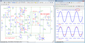
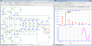
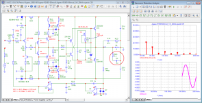
In fact, an isolated 5V power supply does not need to be regulated. Here are the simulation results with a 0.5 V supply ripple at 100 Hz and a 3 V supply with the same voltage ripple. As you can see, this is not reflected in the distortion products.
Attachments

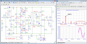
And do you dare to show the THD of this circuit at maximum power 10% before it starts cutting at 20KHz 😉
Sandy, if you were interested in audio equipment and the requirements for its parameters, he would know that odd harmonics from the 7th and higher have the most negative impact on sound quality. The third harmonic in magnetic recording reached 3% or more, but this did not spoil the sound perception in any way.And do you dare to show the THD of this circuit at maximum power 10% before it starts cutting at 20KHz 😉
Aural harmonics also confirm this fact. 🙂
Attachments
Almost anything can be listened to, as long as there is no outright nonsense in it.
Even your scheme with particularly large distortions.
This thread is not about listening.
It is about the possibility of making an amplifier that changes the signal that passed through it as little as possible.
And of course, it is not about non-existent fictional distortions, the fruit of technical incompetence.

This thread is not about listening.
It is about the possibility of making an amplifier that changes the signal that passed through it as little as possible.
Yes, it should be about how to make an amplifier that introduces as little additional distortion as possible, noticeable to the ear, and not measured by Audioprecision in steady state.
But this, Sandy, you can not understand! 🙂
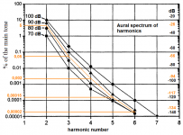
It has been proven that human hearing is insensitive to the second and third harmonics, but has an amazing sensitivity (up to 0.001%!!! - 100 dB) to high harmonics, starting from the fifth (see the graph of aural harmonics). It is they who are guilty of the "transistor" sound.
Above, I have already quoted Nelson Pass's statement about the sound of feedback amplifiers. Here's another one.
John Curl repeatedly gave weights for harmonics from a 1941 German handbook. Even then it was clear that it was necessary to measure not the total harmonic distortion coefficient, but to measure the spectrum, to look at the levels of harmonic components.In one interview with Lamm (known in Russia as V. Shushurin), another fan of amplifiers without general feedback gave the following example: “We have three amplifiers: one has 1-2% distortion, the other has 0.1% distortion, the third has thousandths of a percent. We listen to all this through a speaker system that has 5% distortion. In theory, we should not hear the difference - only The handwriting of the loudspeaker. But we can hear perfectly well that the amplifiers sound different. Paradox, right? The answer to this question is not so easy to find. It took me several years to figure out how to answer it."
The Group Delay graph is more informative - it should have a linear section up to at least 300 kHz and then gradually fall off (not even have a slight rise to at least 1 MHz)Back in the 1950s, Theo Williamson wrote that for a high-quality amplification of an audio signal, it is sufficient that Kr be no more than 0.1% at maximum power. In this case, the harmonic content is virtually undetectable in the most sophisticated listening tests (were talking about tube amplifiers with a short spectrum, this does not apply to modern transistor amplifiers). He also noted that phase shifts between the harmonic components of a complex signal in dynamics, especially on attacks of sounds, have a significant impact on the naturalness of the sound.
Pert 2009 doesn't seem to know that in practice gate servo control with input single-ended Jfet is very far from the parameters that are obtained in the simulation.It is about the possibility of making an amplifier that changes the signal that passed through it as little as possible.
And of course, it is not about non-existent fictional distortions, the fruit of technical incompetence.
And if he really listened in practice to those models that flood the forum, then the servo would have been implemented differently, but no, there is what it is ....
As the classic said: "if the first watt does not work well, then it makes no sense to look further."
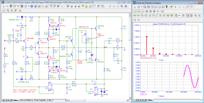
Sandy, and here is the work of the amplifier that you are trying so hard to make fun of in a boorish manner
Sandy, and here is the work of the amplifier that you are trying so hard to make fun of in a boorish manner
Attachments
Pert 2009 doesn't seem to know that in practice gate servo control with input single-ended Jfet is very far from the parameters that are obtained in the simulation.
And if he really listened in practice to those models that flood the forum, then the servo would have been implemented differently, but no, there is what it is ....
Hennady, a forum to share experiences.
Instead of empty reasoning, give an example of the correct implementation of a servo
your manipulations of topologies in models have nothing to do with experience. I see a bunch of errors of a practical nature, which, in the case of practical implementation, would hardly be in the model.Instead of empty reasoning, give an example of the correct implementation of a servo
Moreover, it is a very strange question about the location of a very slow servo circuit in an amplifier, in the presence of a very fast current feedback circuit ...
Hennady, back up your reasoning with at least somethingyour manipulations of topologies in models have nothing to do with experience. I see a bunch of errors of a practical nature, which, in the case of practical implementation, would hardly be in the model.
Moreover, it is a very strange question about the location of a very slow servo circuit in an amplifier, in the presence of a very fast current feedback circuit ...
What is the relationship between fast feedback and servo control? Do you understand the purpose of servo control?
Hennady, I repeat the request: give an example of the correct servo control
Last edited:
- Home
- Amplifiers
- Solid State
- Apex A40 fundamental improvement. (Sandy)