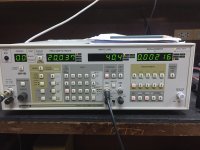
Is this poor THD? This is real measurement on the 200W version.100W-CFA can't be compared to Adeev's crap at all.
Although it unnecessarily complicates the input part (current generators do not need a cascode), without any benefit.
MOS final transistors today when the final BJTs are already 30MHZ is a stupid decision.
Their steepness is 10 and more times lower than BJT. The difference between p/n channels is too big.
All this results in poor THD.
Attachments

Sandy, can you read loop gain graphs? Do they tell you something?
I told you from the very beginning that your amplifier is inoperable, on the verge of generation. Suppose we warmed up your amplifier to a temperature of 60C, set the output to zero and the currents of the output transistors to 25 mA each. It is enough to turn the volume control potentiometer as a constant voltage appears at the output, the amplifier is on the verge of excitation. Now turn it off and turn it on again after cooling to 27C. Oh horror, the quiescent current is 200 mA, the amplifier generates (there is no guarantee that it will not burn out in the generation mode).
As for models from manufacturers, they are rarely close to reality.
Firstly, they are not complete, and secondly, the junction capacitances are often underestimated in them, which brings them closer to ideal transistors. Therefore, the simulation results are more optimistic than they actually are.
Bob Cordell in his books gives examples of how to check models and how to fix them, and also gave a number of models for the most common transistors.
Attachments

Hennady, you are again flooding about nothing. You better bring the requirements for servo control and an example of its correct implementation, which you were asked about earlier, but you still can’t give birth to anything.of course, here even an amateur will find 10 fundamental differences, and there are no stupid ideas here Petr 2009 ....
That's a very good THD.Is this poor THD? This is real measurement on the 200W version.
But I always look at things from another point of view: Can it be even better?
And never just look at THD.
Growth rate and PRSS are also looked at.
Things always come down to acceptable compromises between a set of parameters.
In this 100W-CFA, the small THD is the result of a two-pole frequency response.
When measuring with sine, this gives good results.
But here we do things for ourselves and not to lie to clients with parameters.
But with this type of frequency correction, the signal at the output slowly reaches 0.1-0.01% accuracy.
That's why I never use such frequency correction.
And as you can see it doesn't prevent if things are done right the THD becomes better at 2 times the output power
Attachments
petr_2009
What is the guarantee that your models and mine are the same???
If you could think and understand electronics, you would make the operating modes and the frequency correction so that with your models on your simulator things work correctly.
Cordell left him alone. Yes, he understands a little more, but a little more, and not enough.
And yes, in order for a person to see the possibilities of the scheme, he makes it at the edge of possibilities and.
Simulator and live frequency corrections on a real board are never the same.
The simulator does not take into account the capacitances between the tracks of the board.
Simulation is only the first stage of a project.
And then a test sample. Its measurement. Specifying values, correcting errors......!!!
And then already 0 series. And finally regular production.
I don't expect any negative intelligence prodigy to understand this. 😢 😉
You probably don't know how to read, or you only read what you write yourself.Hennady, you are again flooding about nothing.
everything is written above
if you want to continue to generate nonsense, continue to make servos into the open input, it doesn’t matter to you, as a theoretician ...
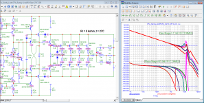
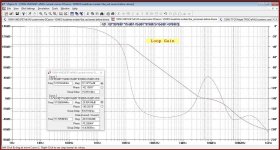
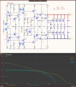
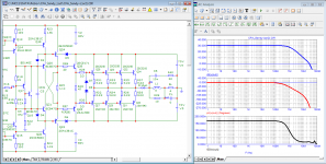
Frequency response at different output voltages +60V, +30V, 0V, -30V, -60V.
The "worst" turns out to be -30V
But even there the phase margin is a huge 82 degrees
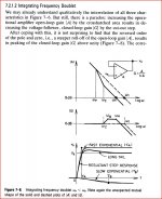
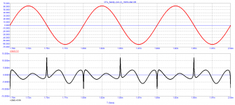
Here there are inductances parallel to the base resistances because when I was making a class A amplifier I saw that the output stage distorts too much. It turned out to be because of the base resistances.
I had to shunt them for the audio range with inductors.
Improves THD for class AB as well
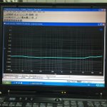
The dependence of the quiescent current on the temperature cannot be seen on the simulators.
Only the transistors of the radiator heat up there, and not at the same temperatures.
You can set the temperature of each transistor individually, but it makes no sense.
This is being fixed on a live board now.
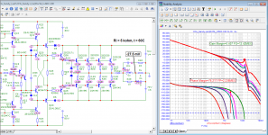
The "worst" turns out to be -30V
But even there the phase margin is a huge 82 degrees
Here there are inductances parallel to the base resistances because when I was making a class A amplifier I saw that the output stage distorts too much. It turned out to be because of the base resistances.
I had to shunt them for the audio range with inductors.
Improves THD for class AB as well
The dependence of the quiescent current on the temperature cannot be seen on the simulators.
Only the transistors of the radiator heat up there, and not at the same temperatures.
You can set the temperature of each transistor individually, but it makes no sense.
This is being fixed on a live board now.
Attachments
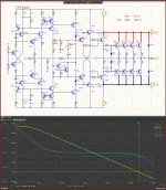
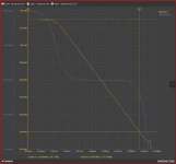
And the rate of rise at 10pF and at 20pF frequency correction.
Sorry, not specifically looking for such a ridiculously high rate of rise
Simply, this is the only but pointless advantage of CFA amplifiers.
And when you don't do outright nonsense it really becomes huge.
Sorry, not specifically looking for such a ridiculously high rate of rise
Simply, this is the only but pointless advantage of CFA amplifiers.
And when you don't do outright nonsense it really becomes huge.
Attachments
I also encountered this, I solved this problem by reducing this base resistance to 1 ohm and shunting the bases of the output transistors of the upper and lower arms with a capacity of 1 μF.Here there are inductances parallel to the base resistances because when I was making a class A amplifier I saw that the output stage distorts too much. It turned out to be because of the base resistances.
I had to shunt them for the audio range with inductors.
Improves THD for class AB as well
Hennady, I see that you have nothing to say about the servo except blah blah blahYou probably don't know how to read, or you only read what you write yourself.
everything is written above
if you want to continue to generate nonsense, continue to make servos into the open input, it doesn’t matter to you, as a theoretician ...
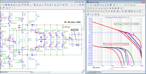
I showed THD only because you said for output mosfets "All this results in poor THD". By the way I used unequal source resistors for N and P type mosfets.That's a very good THD.
But I always look at things from another point of view: Can it be even better?
And never just look at THD.
Growth rate and PRSS are also looked at.
Things always come down to acceptable compromises between a set of parameters.
In this 100W-CFA, the small THD is the result of a two-pole frequency response.
When measuring with sine, this gives good results.
But here we do things for ourselves and not to lie to clients with parameters.
But with this type of frequency correction, the signal at the output slowly reaches 0.1-0.01% accuracy.
That's why I never use such frequency correction.
And as you can see it doesn't prevent if things are done right the THD becomes better at 2 times the output power
Two pole compensation gives small, bat more important, equal THD in whole audio band.
Why two pole compensation is bad, could you elaborate it in more details?
Damir
Sandy, since the telegram channel, I know from you that the last person who understands electronics died 50 years ago, since then you have remained the only one who understands electronics, which is what you talk about in every post. And there is no need to talk about the stages of design, whoever does this knows about it as well as you.
While you are once again practicing stupid storytelling, my works have already managed to visit the audio exhibition at the end of October...Hennady, I see that you have nothing to say about the servo except blah blah blah
I don't care about your verbal litter...
servos for audio amplifiers don't make it the way you're trying to design it, but for the model and your stupid theoretical reasoning, it'll do...
Read J. Dostal there is well written.Two pole compensation gives small, bat more important, equal THD in whole audio band.
Why two pole compensation is bad, could you elaborate it in more details?
Damir
https://books.google.bg/books?id=3V...e=gbs_ViewAPI&redir_esc=y#v=onepage&q&f=false
I very much hope I am not the last.Sandy, since the telegram channel, I know from you that the last person who understands electronics died 50 years ago, since then you have remained the only one who understands electronics, which is what you talk about in every post. And there is no need to talk about the stages of design, whoever does this knows about it as well as you.
And I will be very happy to meet someone who understands these otherwise simple things at least a little.
I'm sure there are still some out there, but they don't deal with audio.
By their works you shall know them, one said long ago, and so they crucified him.
I hope you finally admitted that the inductance at the output of the amplifier is evilI very much hope I am not the last.
And I will be very happy to meet someone who understands these otherwise simple things at least a little.
Sandy, apart from THD, do you know about any other distortions? For example, have you heard what switching (Cross-Over) distortion is?
petr_2009
What is the guarantee that your models and mine are the same???
If you could think and understand electronics, you would make the operating modes and the frequency correction so that with your models on your simulator things work correctly.
Only an amateur thinks that everything is so simple in sound engineering.
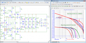
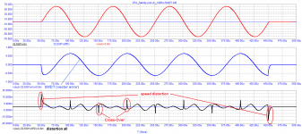
The second time I adjusted the model so that it could work stably, this time without the inductance at the output.
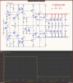
In this case, the loop gain at a frequency of 20 kHz decreased from 40 dB to 33 dB.
For obvious reasons, distortion at a frequency of 20 kHz also increased.
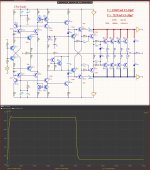
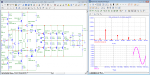
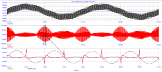
I measured the distortion products at 10 kHz, along with the dominant 3rd harmonic, there is a significant level of cross-over distortion.
I measured the distortion of the burst with a frequency of 10 kHz. High-speed distortion exceeds Cross-Over distortion by 2 times!
But don't be upset, Sandy. The vast majority of developed amplifiers work even worse.
Attachments
-
 01_CFA_Sandy(corr-2)_Bode.png36 KB · Views: 88
 -
 02_CFA_Sandy(corr-2)_Loop-Gain.png40.8 KB · Views: 97
 -
 03_CFA_Sandy(corr-2)_1W_20kHz-spectr.png36.2 KB · Views: 91
 -
 04_CFA_Sandy(corr-2)_Cross-Over.png15.4 KB · Views: 84
 -
 05_CFA_Sandy(corr-2)_10kHz-distortion.png12.3 KB · Views: 80
 -
 06_CFA_Sandy(corr-2)_10kHz-SWDT.png18.2 KB · Views: 91
then it is clear how excusable the prize-winner of the exhibition. Indeed, you can not reveal secrets that you yourself do not know ...While you are once again practicing stupid storytelling, my works have already managed to visit the audio exhibition at the end of October...
I don't care about your verbal litter...
servos for audio amplifiers don't make it the way you're trying to design it, but for the model and your stupid theoretical reasoning, it'll do...
What is an exhibition winner?hen it is clear how excusable the prize-winner of the exhibition.
Or is this your next stupidity?
are you talking to yourself?Indeed, you can not reveal secrets that you yourself do not know ...
you make the same stupid decisions in every scheme - you are a theorist, so keep fantasizing ...
Hennady, I will help you.
Servocontrol systems are the following main types:
1) the inverting Integrator, the control signal phase depends on the connection point in the circuit and, if necessary, is inverted using an amplifier with KU = -1;
2) the non-inverting Integrator, the control signal phase also depends on the connection point in the amplifier circuit and, if necessary, is inverted using an amplifier with KU = -1;
3) Servo system according to claim 1 or according to claim 2, but the output has a post-filter to reduce the penetration of the integrator's pulsations into the amplification tract.
In Ageev’s modified amplifier, I used the third option
Can you justify which option is correct? And why is the option that I used is not good?
There are still subtleties, but I think that you will tell you yourself.
- Home
- Amplifiers
- Solid State
- Apex A40 fundamental improvement. (Sandy)