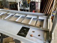
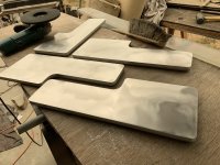
Now a huge amount of calculations has been done.
I have come to the conclusion if the panel is 4 ohm then with 0.025mm aluminum the line width must be 15mm and the line length is about 56m
56m when making a 0.5m wide film the panel becomes about 1800mm high. i will replace ferrite magnets with N 30 neodymium magnets. I would remember that Apogee uses 6 mm distance between the film and the magnets . I simulated with FEMM program that F8 ferrite magnets the force of the magnetic field at 6mm would be 0.05 Tesla. According to my calculations, the 4 ohm panel needs 0.1 tesla force which can be achieved with 50x8x3 N30 neodymium magnets. 0.05 tesla 1 ohm panel produces the same power as 0.1 tesla and 4 ohm panel. Those magnets are 50mm long 8mm wide and 3mm thick . I will need 500 magnets for one panel. please let me know If there are errors in those calculations.
I am now ordering corrugation rods. How much corrugation shortens the straight panel length. example 4" is 3.?" can anyone tell me 🙂
Are making a sort of "Diva"?
Can you show us the FEMM simulation?
Where do you source 50x8x3 N30 neodymium magnets? N35-52 seems to be more common.
Would it not be easier to buy a ready made diaphragm (the one from Switzerland/Vietnam) and build the rest after that?
Can you show us the FEMM simulation?
Where do you source 50x8x3 N30 neodymium magnets? N35-52 seems to be more common.
Would it not be easier to buy a ready made diaphragm (the one from Switzerland/Vietnam) and build the rest after that?
FEMM PICTURESAre making a sort of "Diva"?
Can you show us the FEMM simulation?
Where do you source 50x8x3 N30 neodymium magnets? N35-52 seems to be more common.
Would it not be easier to buy a ready made diaphragm (the one from Switzerland/Vietnam) and build the rest after that?
Sign in to your account
Can someone give me a hint where to buy suitable aluminum foil for Duetta/Diva bass? This won't work, ordering to Finland is impossible.
Granger has some .0007”soft temper in 18” widths
I never tried the soft temper alloy only hard temper but corrugating should give the alloy a slight work harden
Regards
David
I am now ordering corrugation rods. How much corrugation shortens the straight panel length. example 4" is 3.?" can anyone tell me :)[/QUOTE said:If you are using the same DRP rods I used then as an example of the Scintilla panel which is about 50” in length, these rods shrunk the panel 7/8” at 50”
You must factor in the amount of stretch and in my case I pulled the sheet with about (estimate) a 40 pound pull and got within a 1/4” of the shrink.
Since you are making a new layout, you should make your panel first, stretch, and then do your spacing layout of new magnets based on the relaxed panel dimensions instead of the other way around
Regards
David
Hey everybody
First of all I have to thank AVwek. For all the information he has shared for my use as well.
So the intention is to build a bass panel. And its a buddy mid-range treble line source. this line source comes with 7 midrange and 16-21 treble. The size of the bass panel membrane will be 400mm from the bottom and 300mm from the top. the height is 1850 mm. the total height of these speakers is about 2200 mm. These midrange and treble I've done quite a few years. For bass panel I implement neodymium magnets 500 pcs./panel. The film becomes about 6-8 ohms. All supplies have been purchased and plans have been drawn up. Next up is the CNC machining of the panels.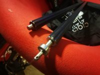
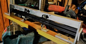
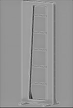
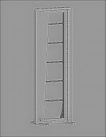


Nice to see someone going for it !
The 2 support wheel sections are better and will keep your panel straighter with less compensating to keep it aligned. I used silicone spray on the rollers and cleaned the panels with acetone on both sides thoroughly.
I noticed some of the anodizing is wearing thru. These rollers need constant cleaning attention so as to not transfer to your finished panel surface.
To get to 6 ohms you would need twice the voice coil length than a Diva panel so the assumption is your adding more turns or tighter spacing specs with neo magnets or much thinner foil ?
Regards
David
Hey.
I have calculated that I can take on that film 56m 15mm wide conductor. At 25 Micron it would be about 4 ohms and at 20 Micron it would be about 6.5 ohms. The conductor should be the entire width of the surface of the film from start to finish, i.e. it is 500mm. thus the height of the panel remains within some limits. at these values the film would be about 1800mm high. Magnets that I have ordered are 50x3x8mm N52 neodymium. the magnets come at 16mm intervals measured from the center. 15mm conductor and 1mm blank 15mm conductor ......
the surface of the corrugator rollers is completely intact. that light spots in the picture are due to when I rotated it blank. those leave when you wipe them.
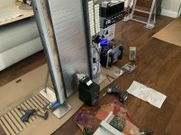
After preliminary tuning and driving it at 100db (c) scale at 20 hz what I find interesting is if you put your hands along the joint where the movable tuning foil section is and the solid frame exsist , you can feel it moving around suggesting a bigger dia. grommet would have better than the one they used.
Will drive it hard for awhile and recheck tuning points to see if it’s drifting around
Music signals will not be an issue but it is there however
After a couple of hours my Krell 100 mono clone hasn’t let the smoke out - yet -
Regards
David
Last edited:
I've been thinking about that same thing, and I've been sure it's moving. It's a good thing it's also been found in In the right tests. I've been thinking that after the tuning. We should be able to lock that up. In that case, the flexibility of those adjusting screws will be lost��Those fastening screws that now allow that move should be able to tighten the panel from the back side I'm trying to come up with some solution to this. Great job again AWERK
Tightening rubber gromets
I too asked myself, if it‘s possible to screw the moveable wooden bar onto the underlaying board (After Tuning).
I guess they did it (rubber gromets) to compensate the membran changes due to temperature changes.
Regards
Olaf
I too asked myself, if it‘s possible to screw the moveable wooden bar onto the underlaying board (After Tuning).
I guess they did it (rubber gromets) to compensate the membran changes due to temperature changes.
Regards
Olaf
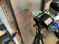
It’s easy to check if solid clamping would result in a better outcome.
I got amplitude swings especially at the lowest tuning freq. ( 32 hz )
More uniform overall the factory way IMO
If you were to rigidly clamp the tuning strip, over time your tuning frequency’s would change with foil wear / movement
If you want consistant tension over time in all conditions it would be best to leave the slight movement afforded by the tightened down grommets under
constant spring tension
They did this way for a reason..,.
FWIW
Break in the foil for a few hours before starting tune
The ( Scintilla only ) has 5 tuning targets
32 hz -6” up from the horiz. clamp strip
47 hz- 6” down from the horiz. clamp strip
39.5 hz - mid point dim. (From top & bottom frequency’s)
Between those 2 areas equal spacing again
35.75 hz lower mid
43.25 hz upper mid
You are tuning for the highest amplitude peak at each frequency
Sweep up & db under power after tightening grommets
(Yes Pete, we are having fun !)
Regards
David
(Yes Pete, we are having fun !)
Regards
David
I see that, I'm envious! Please have me over to see them when you have them playing music.
Hi.
Of those springs that are in those tightening screws. Is there any more detailed information on them. Spring length, wire thickness outer dimension. the force of the spring. In fact, I thought springs the following values.
wire thickness 1,50(mm)
outside dimension 12,00(mm )
inside diameter 9,00(mm)
Unloaded length 22,00(mm) 22,00
Maximum loaded length 11,8(mm)
Maximum mobility 10,20(mm)
Maximum load along the length 90,87 (N)
Spring constant 8,9 (N/mm)

Another tip that made a significant difference was to place a rolled up poster at the exit of your foil.
You might even place it above the exit line height even though I kept it parallel on these 2 Scintilla panels
Without it the exiting crease tends to make cupping down ripples that require more vertical stretching to remove.
You will find the panel lays much flatter before you start your install
Regards
David
- Home
- Loudspeakers
- Planars & Exotics
- Anyone making Apogee bass panels?
 and i will be back
