I spent a lot of time at the weekend reading Fluids thread on his CNC arrays.
At around the time he was assembling and testing there was much debate around wiring etc.
However, i haven't read every page and cannot say i saw a definitive conclusion.
Most unlike me, i am doing some more thinking before build.
Current debates in my mind;
1. Bearing in mind the hexagon reduces panel sizes, is 12mm MDF thick enough or a benefit with thicker? Should all panels be the same, thicker baffle is a problem with back cut away.
2. Each cell will be sealed, does that solve some of what i read as a potential problem
3. What wiring lessons have been learnt
4. What might an optimum stuffing be?
5. Should i build a working cell and test it, bearing in mind i know nothing about that procedure?
M
Series parallel or parallel series, does it make a difference?
5 banks of five units;
1. If the 5 units in each bank are in series then the 5 banks are wired in parallel.
2. If the 5 units in each bank are in parallel, then the 5 banks are wired in series.
Any pros and cons, right or wrong way? tolerance to a broken unit? - if its option 1 and a unit fails, then the whole bank goes down?
M
Sorry if its a really stupid question!
5 groups of TC9s wired together in parallel with each group of 5 wired in series.
You’ll wanna test impedance, phase and working coil of each unit before assembly……thats a lot of testing to be honest….along with a lot of soldering….these tiny driver arrays are A LOT of work……the coulda vs shoulda question will loom as the time passes……
You’ll wanna test impedance, phase and working coil of each unit before assembly……thats a lot of testing to be honest….along with a lot of soldering….these tiny driver arrays are A LOT of work……the coulda vs shoulda question will loom as the time passes……
Thanks Mayhem,
Whats the recommendation for connecting each driver, crimp spade ends to the wire and slide onto the speaker terminals or solder spade ends or solder direct to the driver? I currently favour spade terminals on each spur.
Also in making up the loom, screw block terminals, Wago type i saw, solder up a loom?
Each question has a relevance to ease to dismantle.
By the way, i think i now understand some different motivation in our approach. I am the amateur, will do this only occasionally and have time to spare, you are involved also as work and understandably therefore time matters. For me it really doesn't matter if these new arrays are finished any time soon.....nice but not essential! - no-one pays me anymore, (aahh!) so if the loom takes a week its not a problem!
M
I like to solder to the driver spades….pulling terminals on and off stresses the leads on drivers so I avoid it. I use screw crush terminals on the other end.
Why do you feed it is necessary to test impedans ,phase and coil on each driver????5 groups of TC9s wired together in parallel with each group of 5 wired in series.
You’ll wanna test impedance, phase and working coil of each unit before assembly……thats a lot of testing to be honest….along with a lot of soldering….these tiny driver arrays are A LOT of work……the coulda vs shoulda question will loom as the time passes……
It is absolutely NOT necessary.
Fifty drivers?…..and you would assume that all fifty were consistent?…….i‘m guessing you don’t have a firm grip on the reality of manufacturing.
Interesting points, i imagine those basics would be correct, otherwise the unit would not really "function" as a driver. My guess from being in manufacturing all my working life and receiving bought in components is that there may be some unit to unit variation in response/performance due to tolerances in process but each would function fundamentally. Anyway, I cannot check impedance, having neither the knowledge or equipment but I could look at resistance.
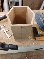
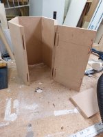
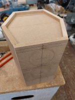
Right now i am working out good ways to assemble the cabinets, teaching myself how to make repeatable angle cuts etc.
Right now i am working out good ways to assemble the cabinets, teaching myself how to make repeatable angle cuts etc.
I have, as many other I know, made such arrays and the drivers are so closely in specs, that you would not gain anything by maching them. Wesayso have measurements of the resonans frequency of his fifty drivers on his thread.Fifty drivers?…..and you would assume that all fifty were consistent?…….i‘m guessing you don’t have a firm grip on the reality of manufacturing.
That seems a very sound proven background to depend on!
For mounting, i am currently thinking something like a self adhesive neoprene tape as the back of the chassis has no gasket.
Anyone have a recommendation for this please?
M
For mounting, i am currently thinking something like a self adhesive neoprene tape as the back of the chassis has no gasket.
Anyone have a recommendation for this please?
M
Fifty drivers?…..and you would assume that all fifty were consistent?…….i‘m guessing you don’t have a firm grip on the reality of manufacturing.
Not that many drivers have a proven track record for production consistency like the TC9. The consistency of these have proven to be way above average.
More than one threads with impedance tests are available.
I made O-rings out of 1/16th inch rubber cord. Super glued ends together. Worked well and was pretty easy to do. Took about an hour to make 50 of them.That seems a very sound proven background to depend on!
For mounting, i am currently thinking something like a self adhesive neoprene tape as the back of the chassis has no gasket.
Anyone have a recommendation for this please?
M
I just used neoprene tape cut to size. (front seal in this case)
Thanks@Mark100, it seems that would need to be quite soft rubber to flatten out nicely, is that correct please?
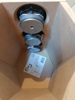
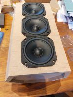
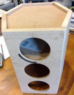
Meanwhile here are the drivers in the mock-up, all fairly easy to do, i only did one divider plate, but think i have proven all the techniques now except how to line the cabinets. i have the felt i've used for lining before, just need to consider how best to attach it. i currently intend to glue all parts permanently but this means i cannot get in there again as the driver hole is smaller than my hand, if i make the back a removable piece its a PITA? if i used neoprene tape i could do the back as well, if its thin...
Meanwhile here are the drivers in the mock-up, all fairly easy to do, i only did one divider plate, but think i have proven all the techniques now except how to line the cabinets. i have the felt i've used for lining before, just need to consider how best to attach it. i currently intend to glue all parts permanently but this means i cannot get in there again as the driver hole is smaller than my hand, if i make the back a removable piece its a PITA? if i used neoprene tape i could do the back as well, if its thin...
Attachments
You bet.Thanks@Mark100, it seems that would need to be quite soft rubber to flatten out nicely, is that correct please?
The rubber is pretty hard really. I just didn't crank down the mounting screws, because I didn't see the TC's frame as all that strong to begin with.
After some fairly careful measuring, I don't think it matters much how well a sealing surface is formed...., I say just do what works easiest.
Thanks for that feedback, i will probably go neoprene tape, however i am intrigued, do your measurements suggest that sealing is not that important?
M
M
I've tried to dig up the old measurements, but they are on some old drive/path I can't find, especially after last weeks migration to yet another new computer.
Damn how keeping 'puters up to date, can be so much work sometimes 🙁
Anyway, here's my best memory of the measurements.
I was testing a single driver in an approx 2 L box. And was only really looking to see how the low end of the TCD changed, with/without gasket or o-ring.
There wasn't that much change but I decided to o-ring anyway...i think more out of simply wondering if it would matter more with all the drivers in one common enclosure...which is what I built.
Like said, I was only looking for how the low end responded, and I also knew I planned on high-passing the line-arrays at 100Hz or above, and using subs. (something i super strongly recommend btw)
I glued up the enclosure box and left the back separate so it will be removable.
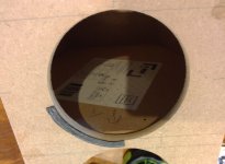
I bought neoprene tape that will form the driver gasket and the back of cabinet gasket.
I did a test quarter of the driver mount with tape.
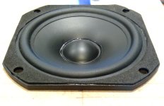
Then i noticed the TC9 front gasket covers a small bolt recess in the face and is not securely fitted.
I could remove it or does it do something in audible terms?
Those that have used TC9's please, should i peel that gasket off as mine will be fastened to the back.
M
Attachments
- Home
- Loudspeakers
- Full Range
- Another corner array project
