Why complicate it with deglitching, PCM1702 is considered as glitch-free due to sign-magnitude architecture, ... finding or creating a low THD analog switch for voltage out hold circuitry is hard, because switch has own THD. Controlling the switch with slowed LRCK can increase jitter problem.
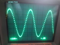
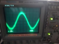
This is pcm1704, posted here Denafrips discrete R2R Multibit
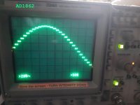
As promised by Ds yes on zero zone no glitches, how about other levels?
A fellow on e2e ti support forum was complaining for glitches
https://e2e.ti.com/support/data-converters/f/73/t/240050
The expert advised nothing but RC filter. The guy used bit banging and here is the result,
before and after.


Bit banging is to emulate a hardware by software. How on earth he programed the emulator?
Last edited:
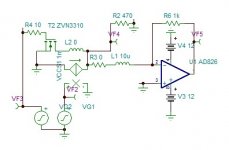
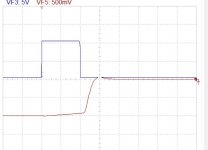
The hike in hold was due to spice model defect of 2n7000. With ZVN3310, not suitable, has near perfect function.
The current sample and hold got invented. How strange that since 4 decades people are struggling to eliminate glitches and no one has thought about such simple solution.

The circuit with opamp.

The current sample and hold got invented. How strange that since 4 decades people are struggling to eliminate glitches and no one has thought about such simple solution.
The circuit with opamp.
Attachments
Last edited:
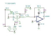
The right switching mosfet is from TI csd15380.
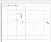
It S/H both polarities.
Bellow is -1.2ma sampled and hold.
Attachments
Last edited:
I don't follow all turns here but I'm fascinated by the topic as well as your willingness and competence to pursue the challenge. And, what's the probability that the best solutions to "standard" problems are all found? Cheers!!
//
//
This is pcm1704, posted here Denafrips discrete R2R Multibit
As promised by Ds yes on zero zone no glitches, how about other levels?
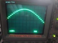
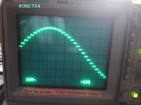
The glitch is neglitible, it is on 1mV scale.
I have not that pro scope.
Attachments
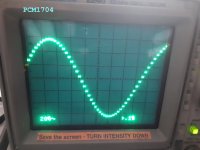
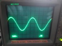
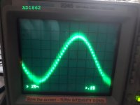
here is the AD1862
Attachments
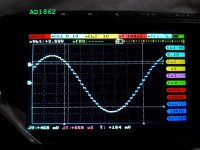
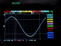
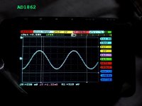
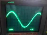
For a signal level -60db, that is 2.8mv peak, if you want to have a modest distortion + noise of 0.1% than the error you should see must not be more than 2.8uv peak!
Your post I am sure will be very helpful for many in the future.
Your post I am sure will be very helpful for many in the future.
I tried a standard R-2R network in the past, feeded by 2s complement data and the glitch was huge, great visible on 1V scale, sometimes over 100mV ... Such glitches are well audible during normal listening 😀
I was looking for an audible glitch at lowest volume on headphones in PCM1704 and AD1862 (even other dacs like AD1865, PCM1702, PCM63, ...) and I didn't hear a tiny sign of that. If an output filter is added on the output, the sound will be modified/colored. Try to create the most transparent filter possible.
Sallen-key filter topology is often used on the output as a post filter, but it also slightly colors the sound.
Before digital era, we could speak so. The most revered pick-up cartridge for Pro use the Shure V had 2.5% 2nd harmonic and 0.5% 3rd with 3%IM. No one could dare to commit lese majesty. When CD replaced the vinyl, the purpose was not to give more beautiful sound but we were promised to receive very precise reproduction.
From day one, the commercial aspect driven by competition, diverted the initial goal to subjective domain dominated by hifi magazine reviews until decadence 32bit 196k.N× OS.
The purpose of this project is to achieve the initial promise by analog approach to deliver the most precise as possible with no compromise.
Before the digital era we could speak so. the most revered pick-up Pro cartridge the Shure V had 2.5% 2nd harmonic, 0.5% 3rd 3%IM. Amplifier were asked to be precise, amplifying subjectively good sources. To put an end to approximate, that came the digital source in CD. We were promised very precise reproduction.
From day one, the commercial aspect took over, dictated by magazine reviews, to drive the technology on wrong track to dead end in decadence of 32bit 196k NxOS.
The consumer simply turned his back to go vinyl.
The purpose of the project is to achieve the initial promise of very precise reproduction, without any compromise using analog approach.
Last edited:
Its already possible for dac reproduction of digital audio to be extremely precise, not only to measurements, but to the ear. The problem is that doing it at that level of performance remains very expensive to implement. Thousands of dollars at retail, maybe more than ten thousand dollars. Bruno Putzeys' Mola Mola Tambaqui DAC being one example: Mola Mola
At that level of performance, trying to do as well with your approach seems unlikely to be successful. For one thing, there are likely too many opportunities for measurable and audible nonlinearities to occur in the analog signal processing you propose.
That said, what you are doing is interesting to many of us because of its novelty. Hope it turns out well enough that you will be happy with the outcome.
Also, one problem that no dac can overcome is the quality of the ADC used. IME with a good enough dac one can hear the limitations of the ADC, and also the limitations of the 16-bit format chosen for distribution. Not to mention the limitations of any original tape recording.
Last edited:
Not true at all. DAC technology has been producing audibly transparent models for at least 20 years. Nowadays they can be had for very low price, as low as built-in DAC in typical disc player on the market.Its already possible for dac reproduction of digital audio to be extremely precise, not only to measurements, but to the ear. The problem is that doing it at that level of performance remains very expensive to implement. Thousands of dollars at retail, maybe more than ten thousand dollars.
Fashion, maybe? In the 1980's, oversampling was the way to solve the weaknesses of the non-oversampling converters. Of course the non-oversampling converters of the 1980's had steep analogue reconstruction filters, no-one would even consider having just a zeroth-order hold as reconstruction filter and taking all the images and the sin(x)/x roll-off for granted.
Last edited:
Evenharmonics has pronounced transparent. The only way you can compare for transparency is by NOS 96 vs 44.1khz NxOS. There you can here how the high frequency percussion instruments are so realistic without treatment.
To get precise deltas, difference between to consecutive samples, I wanted to use a pair of DACs and tie the current outputs to get precise delta. As I have four sample hence, 3 deltas +1 I need 8 DACs/channel. The PCM1702 costing 110$/10 has 0.5% gain precision, per pair makes 1%, adding 1% for I/V converter...... May be I rather find an easy way to adjust manually and use only four DACs/channel.
BTW, The output sigma(integrator) cannot go to DC, I was thinking to limit to 5Hz. Why not make the main converter, which is limited to10khz, to be limited to 500k/10k=50Hz and add a standard mode 5th DAC, with just a 1st order low pass, operating from DC to 50Hz?
BTW, The output sigma(integrator) cannot go to DC, I was thinking to limit to 5Hz. Why not make the main converter, which is limited to10khz, to be limited to 500k/10k=50Hz and add a standard mode 5th DAC, with just a 1st order low pass, operating from DC to 50Hz?
sin wave generator for frequency shifter
The high frequency above 10khz treatment needs to heterodyne the data signal multiplying with a clean sin wave of 44.1 or 48khz, in phase with the sample clock WRCK.
To generate such synchronous wave, I will filter the WRCK with a capacitor switched filter that its clock frequency makes the characteristic frequencies to vary, the LTC1067-50
Plan A is to use a sin generator application where the filter notches the 3rd harmonic of the input square wave and the other harmonics submit to low pass.

The problem to see if the phase remains the same for both 22.05&24khz.
Plan B is to use a high Q band pass filter with linear phase.

Luckily the approximate spice model comes in LTspice to see the results.
The high frequency above 10khz treatment needs to heterodyne the data signal multiplying with a clean sin wave of 44.1 or 48khz, in phase with the sample clock WRCK.
To generate such synchronous wave, I will filter the WRCK with a capacitor switched filter that its clock frequency makes the characteristic frequencies to vary, the LTC1067-50
Plan A is to use a sin generator application where the filter notches the 3rd harmonic of the input square wave and the other harmonics submit to low pass.
The problem to see if the phase remains the same for both 22.05&24khz.
Plan B is to use a high Q band pass filter with linear phase.
Luckily the approximate spice model comes in LTspice to see the results.
Last edited:

This the block diagram of second round.
It consist of 4 PCBs.
1x Sync. I2S 64/32fs to 2xPCM 20fs + several clock generator by double PLL.
2x Digital analog converter + mixer.
1x 2channel SSB (single side band) generator 10k-20khz.
The D/A has 3 sample delays feeding 5 DACs, 4 of which, to generate 3 deltas (difference between 2 samples) and a 5th to add DC to 50hz at the output mixer. An analog clock generates ramp P + its square P2. The 3 deltas and the two Ps enter the analog calculator to create the interpolating additive delta.
The integrator sigma recreates back the signal from 50hz to 10khz.
The SSB has a sin wave converter which shift the frequency of the data, 20khz becomes 2khz and 10khz becomes 12khz with 44.1 sample rate. The result passes through a Quadrant phase shifter after being filtered above 20khz. The two quadrants are re shifted and additioned to generate 10k to 20khz image less signals to be mixed at the output.

I made some errors. The DC-50hz doesn't need a separate DAC, The S₀ DAC I/V output can be used for this purpose after amplifying. The SSB doesn't require the data but the same S₀.
I forgot also that the SSB Hartley modulator needs two 90° phase carriers, but should they be sin waves or square waves can, although I tried it out on simulator.
In fact, the SSB will be my next attention.
- Home
- Source & Line
- Digital Line Level
- Analog Delta-Sigma interpolation DAC