jitter
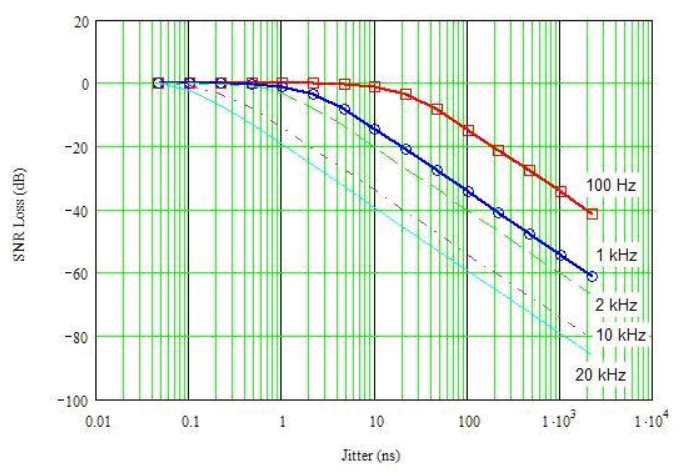
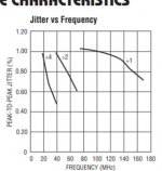
This what I found about jitter troubles. It is 48kfs 16bit measured with random frequency jitter. On can see that 1ns is too much. It is 0.02% for my clock. I will as many have done use double PLL of 74hc9046, which looks the best I found for this. May be someone knows better PLL, but certainly not asynchronous solution. I will also use LM567 to detect the 96khz to switch both the frequency divider and 24/16bit selection.
This what I found about jitter troubles. It is 48kfs 16bit measured with random frequency jitter. On can see that 1ns is too much. It is 0.02% for my clock. I will as many have done use double PLL of 74hc9046, which looks the best I found for this. May be someone knows better PLL, but certainly not asynchronous solution. I will also use LM567 to detect the 96khz to switch both the frequency divider and 24/16bit selection.
Attachments
Analog Devices has some pretty good PLL ICs with built-in LC VCO using an external inductor.
https://www.analog.com/en/products/...-loop/phase-locked-loop-w-integrated-vco.html
https://www.analog.com/en/products/...-loop/phase-locked-loop-w-integrated-vco.html
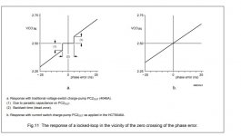
This image is from Stereophile review of streamer using PCM1794.
https://www.diyaudio.com/forums/att...-delta-sigma-interpolation-dac-16khz-60db-jpg
With my DAC, I would get clean sin wave.
When you read the caption carefully, you will see that the shape is due to quantization distortion in the test signal. It's not due to DAC imperfections.
All new PLLs are intended for RF use. My modest frequency is about 200khz extracted from 44.1k to 96khz. I am wondering if I can design a blocking sync oscillator of low jitter, typically used in vertical deflection in TV sets.
The jitter width is considered without taking account about its frequency. The double PLL in series can have much higher than 1ns jitter but if it is bellow 10hz rate, it will harm no one.
Stereophile: Even the sampler remained low bit rate, why the PCM's interpolator working with 24bits didn't recreate the missing points? Where is 127db S/N. With analog interpolator, it doesn't care if it is low level, it recreates back the sin wave even with four samples at any level.
Attachments
An undithered, quantized, 1 kHz sine wave of the level used by Stereophile is just a waveform that switches between -1 LSB, 0 and +1 LSB 1000 times per second. There are no intermediate levels. The interpolation filter can't help it that the waveform fed into it is a kind of three-level square wave rather than a sine. It also can't suppress the harmonics as the 2nd...20th are in the audible range (because it is a 1 kHz signal).
Last edited:
When the DAC receives 20khz, it is also two levels, nearly. If the interpolator is working in 24bit, It should at least transform into triangular. The parasites which are in harmonic, I think they are switching of R2R that my integrator will erase. By the way, the integrator decreases also the distortion harmonics.
I found from the AD link you gave, RF, but interesting PLL AD809. This frequency generator can output 150Mhz with 2° jitter only, that is 0.037ns. I will use it as second PLL as it needs 10Mhz provided by the 9046.
I found from the AD link you gave, RF, but interesting PLL AD809. This frequency generator can output 150Mhz with 2° jitter only, that is 0.037ns. I will use it as second PLL as it needs 10Mhz provided by the 9046.
Last edited:
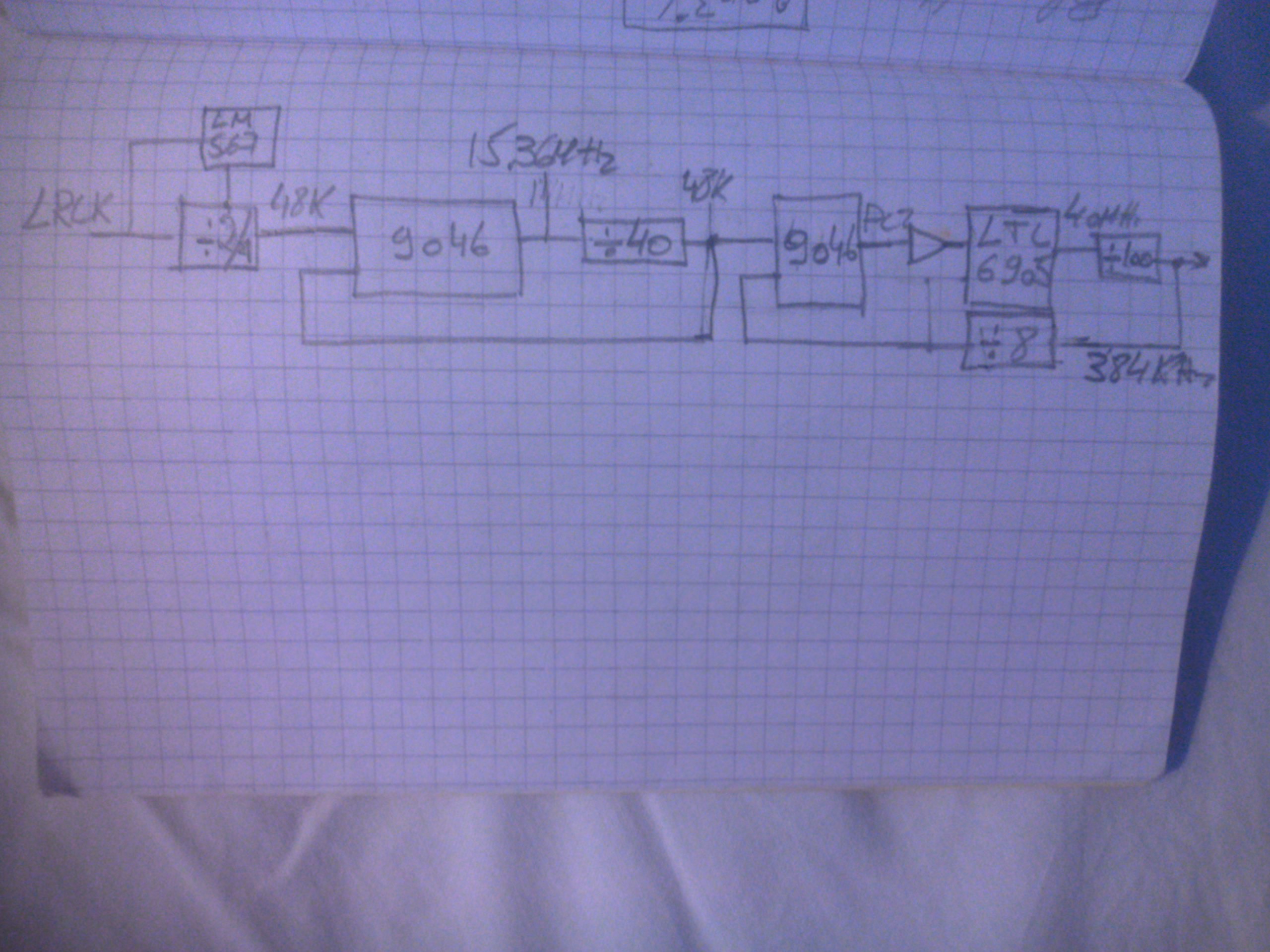
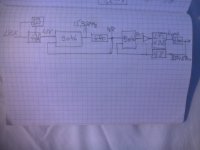
The AD807 has jitter BW of 200khz, so it is useless for me. I prefer to use the LTC6905 current controlled oscillator, It has 0.12ns jitter, I will use a second 9046 only the phase detector2 . To filter the maximum the jitter coming from the first PLL 9046, it use 48khz for phase detection. This is topology I have in mind.
Attachments
When the DAC receives 20khz, it is also two levels, nearly. If the interpolator is working in 24bit, It should at least transform into triangular. The parasites which are in harmonic, I think they are switching of R2R that my integrator will erase. By the way, the integrator decreases also the distortion harmonics.
During the measurement of post #60, the signal going into the interpolator looked like this, with all numbers in LSB of the sixteen-bit word:
0
0
0
1
1
1
1
1
1
1
1
1
1
1
1
1
1
1
0
0
0
0
0
0
0
-1
-1
-1
-1
-1
-1
-1
-1
-1
-1
-1
-1
-1
-1
-1
0
0
0
0
0
0
0
1
1
1
1
1
1
1
1
1
1
1
1
1
1
1
0
0
0
0
0
0
0
-1
-1
-1
-1
-1
-1
-1
-1
-1
-1
-1
-1
-1
-1
-1
0
0
0
0
0
0
0
1
1
1
1
1
1
1
1
1
1
1
1
1
1
1
0
0
0
0
0
0
0
-1
-1
-1
-1
-1
-1
-1
-1
-1
-1
-1
-1
-1
-1
-1
0
0
0
How do you want it to interpolate between those long strings of consecutive 1's and consecutive -1's?
Last edited:
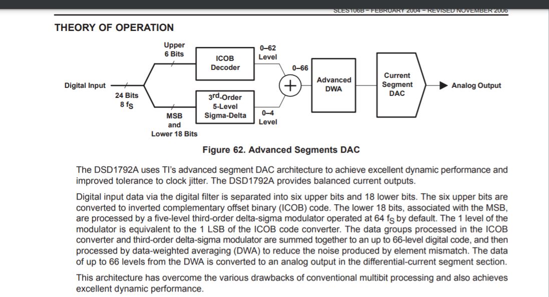
In order to start the interpolation, I needed to know exactly when the analog output arrives. The datasheet of PCMZ1794A speaks nothing about it. Looking in other models which can bypass the digital filter I understood why this DAC needs 4 or 8fs oversampled.
This comes from DSD1792 model. As you can read the output stage even with bypassed digital filter still operates oversampling but why?
The answer showed me that I was cheated from the beginning 😡 from this thread
A NOS 192/24 DAC with the PCM1794 (and WaveIO USB input)
The PCM1794 is not any NOS DAC.
The digital to analog converter is made of ,
This thread gives more details
PCM 1794 Architecture/Concept??
The last 17bits are transformed into single multilevel bit stream and added by coded upper values, all the sacred sampled values rendered corrupt.
So, back to the starting point. I will use the PCM1702 20bit DAC, unlike the precedent, I don't have multiple current outputs, so I will need a poultry of 8 DACs/channel. On the other hand I don't need anymore all the format adapter circuit. The PCM1702 seems the most popular nowadays as on Ali everytime I am looking for DACs, I am proposed a great number of suppliers of this 20bit DAC.
Attachments

Last edited:
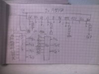
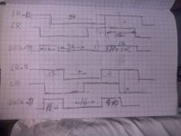
This is the format adaptor for 1702 ×8×2 DACs. Two 64×2 shift registers 14517 +4× 8bit shift registers feed a pair of multiplex to provide required delays 24/16 bit, Right and left data. The LRCK needs to be delayed one clock which is done in the PLL/clock sync circuit.
Attachments
Last edited:
In order to start the interpolation, I needed to know exactly when the analog output arrives. The datasheet of PCMZ1794A speaks nothing about it. Looking in other models which can bypass the digital filter I understood why this DAC needs 4 or 8fs oversampled.
This comes from DSD1792 model. As you can read the output stage even with bypassed digital filter still operates oversampling but why?
The answer showed me that I was cheated from the beginning 😡 from this thread
A NOS 192/24 DAC with the PCM1794 (and WaveIO USB input)
The PCM1794 is not any NOS DAC.
The digital to analog converter is made of ,
This thread gives more details
PCM 1794 Architecture/Concept??
The last 17bits are transformed into single multilevel bit stream and added by coded upper values, all the sacred sampled values rendered corrupt...
That's very interesting! It may explains why I can't see any aliasing images of this DAC. However, its frequency response is the typical one for NOS DACs. Go figure!
In order to start the interpolation, I needed to know exactly when the analog output arrives.
Several of us discussed this in a thread back in 2015. Which is the jitter-sensitive DAC input?
Our conclusion was that while the analog outputs of the PCM1794A can be observed to be updated synchronous with the low-to-high transisitions of BCK, the SDMs and output updates are driven by SCK. So, 64 updates of th analog outputs for each input sample. Conversion jitter is dependent on SCK.
96k 24bit is 2.4Mhz. with 5V it can 3Mhz With 10V supply it can 6.7Mhz max it can 8.3Mhz with 15V.Good luck with 3 MHz
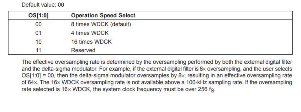
The datasheet specifies the WRCK(LRCK) falling edge is the one that passes the shift register data to output buffer. This why it insist several times that the SCK must be synchron to WDCK(LRCK) and not to BCK. The oversample rate on the output is number of SCK per sample fs. The dddac uses 32 BCK per fs. If it is limited to 16 at 100khz fs than 32 can only function with 48khz.In order to start the interpolation, I needed to know exactly when the analog output arrives.
Several of us discussed this in a thread back in 2015. Which is the jitter-sensitive DAC input?
Our conclusion was that while the analog outputs of the PCM1794A can be observed to be updated synchronous with the low-to-high transisitions of BCK, the SDMs and output updates are driven by SCK. So, 64 updates of th analog outputs for each input sample. Conversion jitter is dependent on SCK.
On e2e ti forum if you ask a question that can not be answered, You get free shipment for your next order, as I won one. If you want to win one also, ask, how the SCK can be made synchronous when the datasheet advises to use PLL1700 fix quartz oscillator.
Last edited:
There is a problem with PCM1702. the datasheet says,
Any number of bits can precede the 20 bits to be loaded, since
only the last 20 will be transferred to the parallel DAC.
This means if I load 16bit data, it will occupy the lower bits. To make it go on the upper ones, I must transform the 16bit data to 24bit, load 4 zeros at the end and delay the data by four clocks to load first 4 dummy ones.
Quelle misère

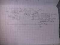
The data is transformed as with 1794 into 2×32 bit only the delays -7 and -8 for data and LRCK becomes -11 and -12 all the rest is identical. In 16bit mode the last four bits are forced to zero and in 24bit the clock is stopped 12bits.
Attachments
Last edited:
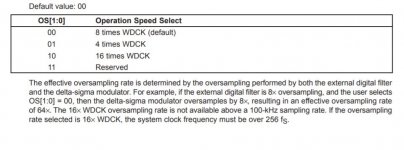
I think Miro was wondering what clock rates your I2S source works at for 96 kHz, 24 bit material and whether your 1970's CMOS logic can handle that.
- Home
- Source & Line
- Digital Line Level
- Analog Delta-Sigma interpolation DAC