ra7,
Thanks info, i could email them first and if they think it's a good idea perhaps with tanks to get good publicity be fine.
Lets see what happens then, at least in 2 weeks xrk971 will own a pair FF105WK and share.
planet10,
Thanks answer kind of you to contribute by loan to tuxedocivic it should actually be a possibility because of this network.
Answer generates new quistions, is there a A7 paper free or what is actual free, will tuxedocivic be interested, and could xrk971 send a Nautaloss/trapezoidal-baffle foam core test box up north to have a better chance to comparison with xrk971 measured ones.
Last edited:
Tony, thanks for the measurement. SB Acoustics makes good quality, competitively priced drivers. In fact, their drivers are probably the most value for money out there right now.
Could you repost the measurement with a 50 db scale and 5 db increment lines? That slope up below 1000 Hz looks smooth on your graph, but it's actually a +5db climb. Can be eq'ed no problem, but I want to highlight how a large scale on a graph makes everything looks smooth. The standard setting should be 50 db range and 5 db increments. If you gate all the reflections, you need little to no smoothing. We don't want to lose the details.
Check out Tux's measurements here (the correct amount of resolution):
http://www.diyaudio.com/forums/full...udio-alpair-6p-tested-against-each-other.html
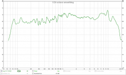
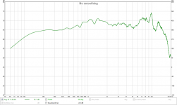
Hi ra7, I took this measurement with REW to get the distortion info. I normally use Holm Impulse but don't have those measurements to hand. I've re-presented with 50db range, with 12th octave smoothing. Unfortunately I don't know how to use the gating in REW otherwise I would show a gated measurement (which would definitely be preferable. It would probably have resolution down to about 200Hz.
I've also attached the impulse response, you can clearly see a substantial reflection at around 22 ms.
Tony.
Attachments

I said earlier that i would be doing T/S measures this week.
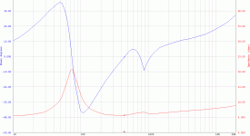
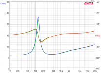
Here is the CHN-70. The magnitude of impedance bump at the transition frequency is consistent with Mark's data.

The little VIFA has a VERY smooth impedance cutve -- xonsistent with my guess that the cone/suspension id heavily damped (leading to both smooth FR and poor DDR), so it is hard to see the transition frequency but i would say just above 2kHz,

Graphs generated with Smith & Larson Woofer Tester 2
dave
Here is the CHN-70. The magnitude of impedance bump at the transition frequency is consistent with Mark's data.
The little VIFA has a VERY smooth impedance cutve -- xonsistent with my guess that the cone/suspension id heavily damped (leading to both smooth FR and poor DDR), so it is hard to see the transition frequency but i would say just above 2kHz,
Graphs generated with Smith & Larson Woofer Tester 2
dave
Attachments
Thanks answer kind of you to contribute by loan to tuxedocivic it should actually be a possibility because of this network.
Ryan lives close so he can come by or they can get dropped off.
FF105wKeN (soon), SS 10F, likely more. The weather is nice enuff at the moment they could be done outside.
and could xrk971 send a Nautaloss/trapezoidal-baffle foam core test box up north to have a better chance to comparison with xrk971 measured ones.
Or XRK could make a better test facility as Barleywater has suggested.
dave
I could do it but if do them on a sheet of plywood outside so not exactly like xrk's.
I keep planning on buying soundeasy. Was gonna wait until June when I'll be in the states to save on shipping. But I wouldn't mind buying it soon rather than later as I have a big JBL project is like to use it with also. I should be down in Vic one of these spring weekends, but not sure when and Dave probably is busy with things too, so it all depends.
I keep planning on buying soundeasy. Was gonna wait until June when I'll be in the states to save on shipping. But I wouldn't mind buying it soon rather than later as I have a big JBL project is like to use it with also. I should be down in Vic one of these spring weekends, but not sure when and Dave probably is busy with things too, so it all depends.
All these results show high correlation between drivers <4kHz; all of which bear no resemblance to results obtained using a flat baffle of any significant size. Yes, standard IEC baffle quoted for use with drivers <8" is inconveniently large.
For objective comparison that allows participating contributors to verify other's results, a common test setup must be used. I suggest a smaller simple rectangular baffle scaled down from the standard IEC baffle since topic is for drivers 4" or less.
Use of term "gate": Gating is truncation of all samples outside of gating range to zero. A jump discontinuity occurs at the gate boundary and can cause significant in frequency response measurements that go well beyond loss of low frequency information.
Gating is use of rectangular window. I suggest use of Blackman window or Blackman-Harris 4 term window, or Blackman-Harris 7 term window. These windows can be set to somewhat longer values. For example: In REW a Blackman-Harris 7 term window set to 8ms attenuates signal at 5ms by about 39dB.
Recording of music tracks for sharing as comparison is an excellent concept when constraints are used. Sure, gross differences can be heard when played back through loudspeakers, but vagaries of each speaker and room of listener intrude. Quality over ear head phones work much better, but are relatively expensive and may be exclusionary to many who may wish to participate in objective discussions. Earbuds that seal ear canal are great for these purposes. The low frequency performance of even <$10 Skullcandy earbuds rival low frequency performance of any 4" speaker, regardless of how it is mounted.
A major complaint of music recordings for comparison is choice of music. This is readily circumvented by use of convolution. Those who care to participate in this discussion need convolve impulse response of subject driver/speaker provided by the measuring party with music of own choosing.
Measurement microphones: Most have sufficiently flat response for use without correction curves; which never are applied to exported IR wave files. 1/2" diameter models such as ECM8000 should be used at 90 degrees to avoid rising response due to baffle effects of the surface area of the microphone tip.
-----------
Here is a result from my latest DSP based speaker:
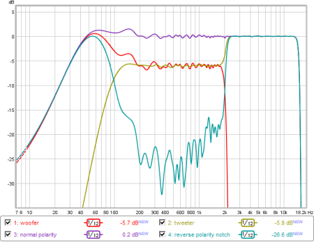
From thread that I posted:
http://www.diyaudio.com/forums/mult...sum-monopole-dipole-speakers.html#post4227362
Ok, let's agree on a standard baffle that is manageable. So scale IEC baffle down to 4 ft wide? My measurements at 0.5m with 4ms gate or window is good down to 250Hz. 1st small reflection is 6ms and gate is 4ms.
I use "gate" but in REW it is a window function really. I think default is Hanning. You like Blackman better?
I did not know mics should be used 90 deg. The lip on my UMM-6 is quite small - a lot smaller than the Behringer EC. It is 0.25in dia tube I believe.
I don't understand what you mean by convolution to solve choice of music problem.
Maybe we vote on three or five test songs each 40 seconds long which allows conversion to MP3 at 192kbit to fit as an upload. I know that a lot of people don't like MP3 compression but flac files are huge.
Xrk, a 4ms is not all that good below 2/0.004 and possibly more like 2.5 or 3/0.004. I haven't been looking below about 600 on your plots and I don't think others should either. Just an FYI.
Thankfully the >600hz is really the important part. And <150hz is strongly influenced by the box. So there's just a couple octaves that aren't useful in this situation and they're not that significant. Also, most drivers are well behaved in the 150 to 600hz range.
If you want a general discussion, nothing wrong with your setup. If you want to pass judgement...
.....Or XRK could make a better test facility as Barleywater has suggested.
dave
Yes he could but think xrk971 been flexible he had changed spec for setup 3 times and published all three this thread, tendency the plots are same for an untrained and trained even maybe commercial ones can probably use data some way down the road, Overkill Audio said #275 test methods are more than accurate enough for any open minded DIY'er. Also CHN70 plot ended up confirmed at the Japanese site. The good thing all the discussions around test setup is it's very educating, at least for me.
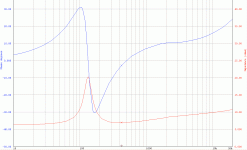
Thanks your impedance plots CHN70, for me the phase mirror looks strange but I'm not a pro and will have to investigate. Your one is different than xrk971 one and will keep an eye in future to see other ones to discover if i have to prepare excuse for the words said about datasheet out of spec.
Regarding if DATS in this case v1 is reliable tool attach plot 4 x TC9FD drivers very much match yours.
Attachments
Hi ra7, I took this measurement with REW to get the distortion info. I normally use Holm Impulse but don't have those measurements to hand. I've re-presented with 50db range, with 12th octave smoothing. Unfortunately I don't know how to use the gating in REW otherwise I would show a gated measurement (which would definitely be preferable. It would probably have resolution down to about 200Hz.
I've also attached the impulse response, you can clearly see a substantial reflection at around 22 ms.
Tony.
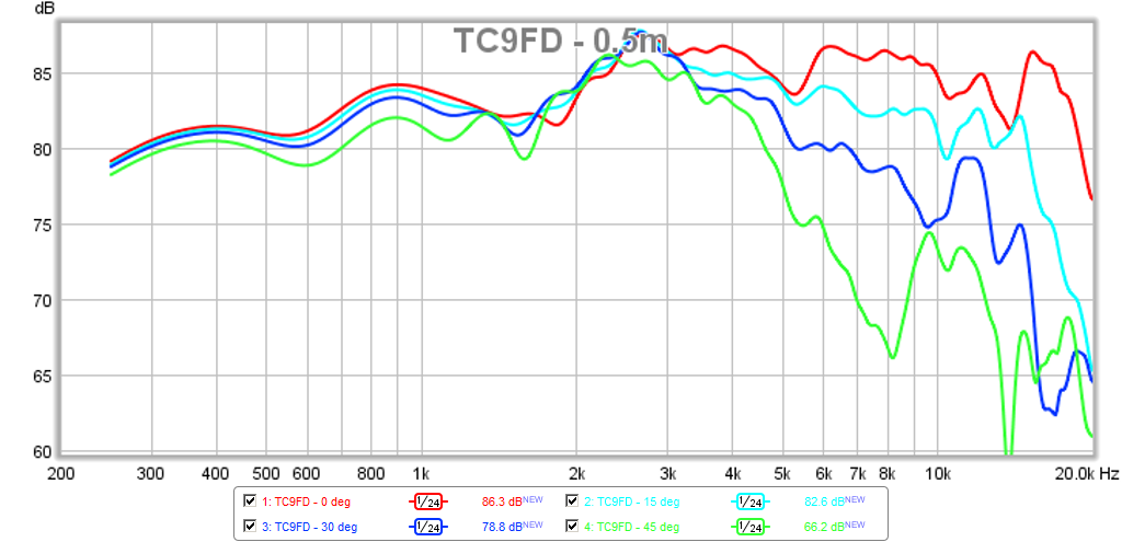
Thanks for redoing the data with the gate/window. Looking at your IR, there is a non-negligible reflection at about 5ms (~33 inches away). I think this may be causing the small rippling in your higher frequency (2khz to 5khz) data. It is a small 0.5dB effect so not a big deal. Still looks like an excellent well balanced driver though - certainly right up there with the rest of the lineup I have tested with exception of earlier HF falloff.
Last edited:
BYRTT, usually Madisound accepts returns no questions asked within 30 days. Drivers could be shipped to X, tested and X can then return them, though he would have to pay shipping both ways. Members could chip in for the shipping. It will be much less than just buying the drivers.
I wasn't going to get involved in this thread again, nor have I any intention of discussing units, testing, subjective, objective or anything else related. However, this made me sit up. Bolt up.
Madisound may have a return policy, but it was certainly not going to have been set up as a means for people to 'try before the buy.' A purchase goes both ways: it is a contract between purchaser and the vendor that is supposed to be made in good faith with intention. Obtaining drivers from a vendor with no intent of keeping them is deception. I can't speak from a purely legal background, but as-is, I for one would regard this as ethically dishonest at best. Madisound would regard this with an extremely jaundiced eye indeed. As would the majority of other vendors. It costs them time, it causes them problems re warranties, it costs them money. The same would apply to most manufacturers. Some may be willing if approached honestly, i.e. you ask them up front to supply you with free drivers to play with -they are the ones who state as much. Here, and I quote verbatim from their website, is their return policy:
Our products have a one year warranty against manufacturer defects. Return the defective item(s) to us with a complete explanation of the problem. Please include your contact information with a daytime phone number (or email address) to reach you for additional information.
Products received in damaged condition must be reported immediately, and the original shipping carton should be retained for inspection.
Package returns carefully, manufacturers will not warranty damaged products. We handle most warranty claims directly, and will usually exchange defective units within two weeks of return.
Disputes over driver performance will be handled through the manufacturer.
Madisound will accept returns of purchases for refund (not including crossovers or special orders) for a period of 45 days after purchase. Items must be returned in unused condition. There must be no evidence of mounting or soldering.
I read some posts where people claim manufactor's data to be like xrk971's and just one driver differs. Now I compared Vifa's frequency respons with here and those don't match very well. Loudest point xrk971 for Vifa 1m around 2500hz and like 87.5dB, Vifa's own around 83.5dB there, xrk's respons dropping a little to around 86dB around 14khz, Vifa's own rising to around 92dB there. So for that range xrk971 graph start 4dB above Vifa's own and end 6dB below Vifa's own published frequency respons.
I read some posts where people claim manufactor's data to be like xrk971's and just one driver differs. Now I compared Vifa's frequency respons with here and those don't match very well. Loudest point xrk971 for Vifa 1m around 2500hz and like 87.5dB, Vifa's own around 83.5dB there, xrk's respons dropping a little to around 86dB around 14khz, Vifa's own rising to around 92dB there. So for that range xrk971 graph start 4dB above Vifa's own and end 6dB below Vifa's own published frequency respons.
Note that my 0.5m data was obtained at 2.83v minus 6dB (or 0.71v) on drive to approximate 2.83v at 1m. It may not be the same as distance and voltage not identical.
Look at this curve, which perhaps would be the closest comparison although still not at same drive level. I was not trying to match absolute SPL exactly. I did check to see if my absolute SPL is close though. The discrepancy at 14kHz with factory at 92dB vs my measured unit may be variability in driver and in my case, a good thing to have lower peak there. But general shape and trend is consistent with factory plots.
Last edited:
subsequent measurements of CHM-70 impedance still show the extreme resonance ~ 900 Hz , leads me to believe that the other measured responses in this thread are valid and not broken. Is it a feature or blemish, I reckon its a matter of taste.... like most westerners prefer their Chinese food with extra MSG and sweeteners.
DDR pfft.. that means double data rate memory.. pick yer 'marketing' acronyms wisely! Downwards into the noise and muck where it cant be measured , then your arguments by are valid by default ..nonsense. Marketing at its finest eg they often turn a engineering disadvantage upside down into a special feature.
DDR pfft.. that means double data rate memory.. pick yer 'marketing' acronyms wisely! Downwards into the noise and muck where it cant be measured , then your arguments by are valid by default ..nonsense. Marketing at its finest eg they often turn a engineering disadvantage upside down into a special feature.
Last edited:
subsequent measurements of CHM-70 impedance still show the extreme resonance ~ 900 Hz
There have been 3 impedance measures of the CHN70. XRKs, mine & the factory data. Magnitudes of 6, 1, 1 dB respectively. The last 2 taken with the more accurate tools.
As has been explained earlier every FR driver will have 1 or more of these resonances marking where the driver is transitioning from pistonic to resonant behaviour.
dave
explained?
pistonic transition behavior can be explained with differences from on-axis to off axis responses and it's always higher up than 900Hz for this 3" size, mostly it's a smoother transition until cone breakup. eg not a spike as shown on one driver. I believe it's internally something else, IMO related to cone to surround materials / interfaces eg resonance. only the MA knows for sure, but they'd rather suppress that dialog.
pistonic transition behavior can be explained with differences from on-axis to off axis responses and it's always higher up than 900Hz for this 3" size, mostly it's a smoother transition until cone breakup. eg not a spike as shown on one driver. I believe it's internally something else, IMO related to cone to surround materials / interfaces eg resonance. only the MA knows for sure, but they'd rather suppress that dialog.
The dip at 700Hz and its associated impedance wiggle is most likely the stereotypical cone edge/surround resonance that one sees at these frequencies with anything other than completely rigid metal or ceramic type cones. It's not going to make anything unlistenable, neither really would the peaky nature of some of these FR drivers either, but it would make them unnatural, unbalanced and uneven. Sure it's probably quite nice to listen to and often inoffensive, but it is NOT accurate sound reproduction.
The only caveat to those comments above are if a driver has a peaky nature throughout it's midrange, say from 700-3kHz. Dips are fine, peaks are most certainly not and they will add a forwardness to the sound, if coupled with less than ideal paper cone breakup that will be unpleasant, especially in the long term. These qualities would be especially apparent if no bafflestep filter were in place.
I often find it crazy the number of people who use their full range drivers with absolutely no filters in place. Just because a driver is full range does not make it immune to the ills that loudspeakers typically suffer from and also do not make them immune to the laws of physics. Unless the loudspeakers are wall mounted, corner mounted, shoved into a corner or have some interesting driver arrangement like some of the top and front firing designs, then you will absolutely need a bafflestep filter unless you're trying to compensate for it with a wonky cabinet alignment that's far from perfect to start with. This thread has been quite indicative of why some simple notch filters, along with a baffle step compensation filter would improve the overall accuracy of pretty much all the drivers under test. I have built several full range designs and all sound great, but they DO need filtering to be at anything close to their best.
data for which driver?
Hi there w: Which driver's data are you presenting? ...regards, Michael
OK windows, thanks xrk that gave me what I needed to work out how to present gated data in REW 😉 Attached windowed at 21ms.Tony.
Hi there w: Which driver's data are you presenting? ...regards, Michael
- Status
- Not open for further replies.
- Home
- Loudspeakers
- Full Range
- An Objective Comparison of 3in - 4in Class Full Range Drivers