SS10F/8422-03 and VifaTC9FD-18-08

最後にScanSpeak版10F/8422-03とVifa版TC9FD-18-08の周波数特性をgifアニメにしてみた。出力音圧レベルの差程度しか違いがないのに、試聴で受ける印象が違うのはなぜなんだろう? おもしろいね。
It wouldn't have happened because none of the other manufacturers wish to engage members on an open forum, for obvious reasons.
jeff
I don't understand. Mark didn't engage us either. I think xrk was hinting at fanboyism perhaps?
Irrebeo,
I don't read Japanese. What box was this tested in? Looks like both drivers are similar with Scanspeak having a bit more smoothness up on top. Both need serious BSC and both have some room cancellation dips going on or this is the output of a TL. Where is this link from?
That is kind of creepy to have a plot that is alive and flips back and forth.
Last edited:
My Brain Hurts
WOW! 380 posts and counting, (more if somebody sneaks one in while I am typing).
I have several observations;
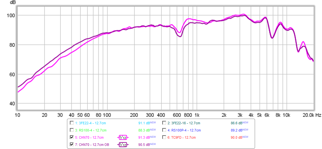
1, This is an objective comparison of several speakers done in the same baffle. I think the raw data and graphs should be in a sticky post without all the conversation surrounding the information. This is very good work. Thank you.
2, There was a lot of unnecessary and unprofessional arguing about the deviation of the Mark Audio CHN-70 graph from the published specifications. Through all the arguing, nobody gave an unbiased look at why xrk971's readings were different other than "bad equipment".
If x's enclosure is a uniquely bad one for that particular Mark Audio speaker, that is not something to complain about; it is actually valuable information.
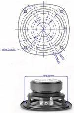
By looking at the speaker's dimensions, I notice that it has a combination of a very shallow metal basket combined with an extremely large magnet mounting plate and magnet. ALL the back wave goes sideways. My hypotheses is that in x's narrow and deep Nautiloss enclosure, the back wave was pretty much choked and not able to use the infinite baffle nature of the box. That may explain some of the plot's problems. I would like to see a plot with the speaker back mounted on a simple flat open baffle.
Please, let's quit arguing and do a bit more experimenting and learning.
WOW! 380 posts and counting, (more if somebody sneaks one in while I am typing).
I have several observations;
1, This is an objective comparison of several speakers done in the same baffle. I think the raw data and graphs should be in a sticky post without all the conversation surrounding the information. This is very good work. Thank you.
2, There was a lot of unnecessary and unprofessional arguing about the deviation of the Mark Audio CHN-70 graph from the published specifications. Through all the arguing, nobody gave an unbiased look at why xrk971's readings were different other than "bad equipment".
If x's enclosure is a uniquely bad one for that particular Mark Audio speaker, that is not something to complain about; it is actually valuable information.
By looking at the speaker's dimensions, I notice that it has a combination of a very shallow metal basket combined with an extremely large magnet mounting plate and magnet. ALL the back wave goes sideways. My hypotheses is that in x's narrow and deep Nautiloss enclosure, the back wave was pretty much choked and not able to use the infinite baffle nature of the box. That may explain some of the plot's problems. I would like to see a plot with the speaker back mounted on a simple flat open baffle.
Please, let's quit arguing and do a bit more experimenting and learning.
Attachments
WOW! 380 posts and counting, (more if somebody sneaks one in while I am typing).
I have several observations;
1, This is an objective comparison of several speakers done in the same baffle. I think the raw data and graphs should be in a sticky post without all the conversation surrounding the information. This is very good work. Thank you.
2, There was a lot of unnecessary and unprofessional arguing about the deviation of the Mark Audio CHN-70 graph from the published specifications. Through all the arguing, nobody gave an unbiased look at why xrk971's readings were different other than "bad equipment".
If x's enclosure is a uniquely bad one for that particular Mark Audio speaker, that is not something to complain about; it is actually valuable information.
By looking at the speaker's dimensions, I notice that it has a combination of a very shallow metal basket combined with an extremely large magnet mounting plate and magnet. ALL the back wave goes sideways. My hypotheses is that in x's narrow and deep Nautiloss enclosure, the back wave was pretty much choked and not able to use the infinite baffle nature of the box. That may explain some of the plot's problems. I would like to see a plot with the speaker back mounted on a simple flat open baffle.
Please, let's quit arguing and do a bit more experimenting and learning.
I suspected same thing.
Plain OB vs Nautaloss. Been there done that.
Irrebeo,
I don't read Japanese. What box was this tested in? Looks like both drivers are similar with Scanspeak having a bit more smoothness up on top. Both need serious BSC and both have some room cancellation dips going on or this is the output of a TL. Where is this link from?
That is kind of creepy to have a plot that is alive and flips back and forth.
looks like the Ikea bowl 🙂 in listeningposition respons is flat
ƒXƒs�[ƒJ�[‚ÌŽü”g�”‘ª’è�E‚»‚Ì2 ‚¨‚ñ‚É‚å‚Ì�^‹óŠÇƒI�[ƒfƒBƒI/ƒEƒFƒuƒŠƒuƒ�ƒO
I don't get the why of posting this Vifa/Scanspeak graph as it does not seem to be a measurement valid for this thread. If you were looking for a validation of the official Vifa published measurements look at Zaph's website. He posted measurements of the Vifa showing a remarkable resemblance to the original published graphs.
If I remember correctly Owen (member name opc on here) supplied the 2 samples back in 2011. Here's one of the two graph's already uploaded here on the site.
Source of the graph: http://www.diyaudio.com/forums/multi-way/193015-stupid-cheap-line-array-10.html#post2798193
So that matches the rising high frequency response from the published specs from a driver in 2011.
Last edited:
hey planet10 - does it still take around 15-20 minutes to gather a high resolution full range Z graph from a Woofer Tester 2?
I don't know. I guess it depends on what you mean by high resolution. I was/am going to ask the guys on tips to get the best impedance curve (they have always been really helpful -- i even got a special beta version of the software to sort a bug that the Alpair 7p evoked).
I only use it for T/S matching. I did get some tips that at least halved the time it takes to do that Probably a couple minutes per driver (i measure each one twice and use the 2nd one)
I kilt two of them over a period - accidentally had a WT2 lead short to an amplifier ground and they melted down
Being a current amp they should survive a short, it is open circuit that stresses them
Are you sure little bumps represent mode transitions rather than simple parts resonances?
I am going by what Mark said when i quizzed him about the bump in the EL70. I have found him to be knowledgible, honest, and tests all the cones (not each one, but each model) with laser interferometry so he should know. He was Ted Jordan's apprenticeand Ted has talked about this since forever.
dave
I don't get the why of posting this Vifa/Scanspeak graph as it does not seem to be a measurement valid for this thread. If you were looking for a validation of the official Vifa published measurements look at Zaph's website. He posted measurements of the Vifa showing a remarkable resemblance to the original published graphs.
If I remember correctly Owen (member name opc on here) supplied the 2 samples back in 2011. Here's one of the two graph's already uploaded here on the site.
Source of the graph: http://www.diyaudio.com/forums/multi-way/193015-stupid-cheap-line-array-10.html#post2798193
So that matches the rising high frequency response from the published specs from a driver in 2011.
Indeed 2 reasons, SS 10F was mentioned couple of times and no other measurements than those presented here have peakrespons for ~2.5khz with Vifa, they all have peakrespons at ~14khz.
Irrebeo,
I don't read Japanese. What box was this tested in? Looks like both drivers are similar with Scanspeak having a bit more smoothness up on top. Both need serious BSC and both have some room cancellation dips going on or this is the output of a TL. Where is this link from?
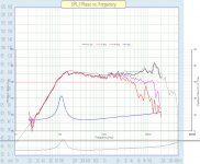
There is something funky about those graphs. First off all, the scale is 120db, it is completely useless for evaluating the response. Secondly, one does not expect such a large slope in the response. Something is off.
I suspected same thing.
Plain OB vs Nautaloss. Been there done that.
Yes, a baffle 20" x 30" is a convenient choice. Microphone at 2ft/50cm is also good compromise in home environment. Baffle placement 4ft from front wall, at least 4ft from sidewalls, and with driver center 4ft from floor. Given average ceiling height of about 8ft this will provide measurements free of room reflections of 5-6ms. Second measurement with microphone about 1/4" from dust cap provides better low frequency data; at close distance direct to reflected ratio is very high and windowing to 16-30ms compares favorably to shorter windows. These may be referenced to several examples of driver in 20-60 liter sealed box, representing infinite baffle below about 300Hz.
EdKennedy:
ALL the back wave goes sideways.
Not at all. Much radiation hits back of basket/face of magnet structure and is reflected. A significant amount of the reflected energy passes through driver membrane. Dimensions of magnet become significant for high frequencies; when distance from membrane to magnet is 1/4 to 1/2 wavelength the reflected energy radiating back through membrane combines with front of membrane radiation resulting in peaks and dips. Secondary reflections from back of membrane set up resonance. In the case of MA drivers and others with shallow profile cone the situation is worse than with drivers such as Vifa TC9FD, were steeper profile of cone radiates more energy away from magnet, and reflections from magnet meet cone at higher angle of incidence with correspondingly less energy passing through cone, with more being reflected side ways.
There is something funky about those graphs. First off all, the scale is 120db, it is completely useless for evaluating the response. Secondly, one does not expect such a large slope in the response. Something is off.
Scale is funny and seems intended to show little difference between the 2 units. The slope in the respons is as close to Vifa's measurement as Zaph is, both are off, the Japanese shows a little bigger slope, Zaph a little less slope than Vifa themselves.
I wouldn't say Zaph's measurements are that far off from the original.
Once you adjust the scale to match they are actually quite close:

One might argue which graph is more accurate but you'd have to agree that they are similar.
This does show how important the scale is if comparing drivers. They have to be exactly the same to get a good first impression.
The Japanese graph shows many artefacts that are (too) similar between the Scanspeak and Vifa. So were looking more at a speaker/room graph than a driver in that case.
Once you adjust the scale to match they are actually quite close:
One might argue which graph is more accurate but you'd have to agree that they are similar.
This does show how important the scale is if comparing drivers. They have to be exactly the same to get a good first impression.
The Japanese graph shows many artefacts that are (too) similar between the Scanspeak and Vifa. So were looking more at a speaker/room graph than a driver in that case.
Attachments
Last edited:
Yes lineout graphs either on 2.5k or 14k (highest output xrk or Vifa's graph) and Vifa's own is in between Japanese and Zaph. xrk's looks more like the Zaph/Vifa off axis respons btw ,is baffle material functioning as cone too, they did use the material with exciters with some succes in another thread, is microphone membrane mounted angled in xrk microphone??
Yes lineout graphs either on 2.5k or 14k (highest output xrk or Vifa's graph) and Vifa's own is in between Japanese and Zaph. xrk's looks more like the Zaph/Vifa off axis respons btw ,is baffle material functioning as cone too, they did use the material with exciters with some succes in another thread, is microphone membrane mounted angled in xrk microphone??
Baffle is triple ply sandwich made of foam core - double layer heavy duty cardboard - foam core sandwich glued with hot melt. Quite stiff and sort of having some constrained layer damping (CLD) for self dampeding of panel resonance. If single layer, I would say it may contribute but probably not in this case.
I used mic at 0 deg incidence so not angled. The lip on the mic housing to the membrane is very thin (less than 1mm) so I don't think there is a baffle edge effect of the mic similar to the thicker barrel ECM6000 mics from Behringer.
Last edited:
For this OB measurement of the CHN 70, the OB size was 24in wide x 36in tall.Yes, a baffle 20" x 30" is a convenient choice.
I have been seeing a lot of posts on the Jordan Eikona 2 - that would be a really interesting driver to test. Might be one of the more expensive units out there though. If anyone wants to post measurements they have taken in a sealed box or otherwise that would be great.
on the other end of the Jordan, you might include the old MCM 5"? - - it measured pretty flat but lacks the highs of the Vifa and Faital Pro entries
MCM Audio Select 5'' Full Range Monitor Driver | 55-1595 (551595) | MCM Audio Select
MCM Audio Select 5'' Full Range Monitor Driver | 55-1595 (551595) | MCM Audio Select
I cant criticise the measurement technique, as I do not have the time or wherewithall to do so.
But serious measurements with foamcore baffles ....that I can criticise.
Kudos for the investigative work, but maybe a real baffle/box would be a good idea???
But serious measurements with foamcore baffles ....that I can criticise.
Kudos for the investigative work, but maybe a real baffle/box would be a good idea???
- Status
- Not open for further replies.
- Home
- Loudspeakers
- Full Range
- An Objective Comparison of 3in - 4in Class Full Range Drivers