Madisound may have a return policy, but it was certainly not going to have been set up as a means for people to 'try before the buy.' A purchase goes both ways: it is a contract between purchaser and the vendor that is supposed to be made in good faith with intention. Obtaining drivers from a vendor with no intent of keeping them is deception. I can't speak from a purely legal background, but as-is, I for one would regard this as ethically dishonest at best. Madisound would regard this with an extremely jaundiced eye indeed. As would the majority of other vendors. It costs them time, it causes them problems re warranties, it costs them money. The same would apply to most manufacturers. Some may be willing if approached honestly, i.e. you ask them up front to supply you with free drivers to play with -they are the ones who state as much.
Scott, you are right on this one. I was wrong and probably wasn't thinking clearly enough. Buying drivers knowing that you are going to return them is not right.
In my defense, I have returned drivers on three occasions. Twice they were defective right out of the box, I mean gross defects, such as the cones being deformed. The third time I bought a line up of compression drivers to test and after choosing the one I was going to use, returned the ones I did not need. I did end up keeping 3 of the six in the end. Note that the performance of compression drivers is heavily dependent on the horn, and I wanted to test the drivers on the horns I had. I paid shipping both ways, and the restocking fee, and returned the drivers unblemished, i.e., without scuff marks and such.
only the MA knows for sure
The Mark Audio drivers are unusual in have 1 primary impedance bump, most FR (that i have measured) show a train of bumps.
I first asked about this on the EL70. Mark supplied the explanation. Backed up by laser interferometry.
dave
>>> Unless the loudspeakers are wall mounted, corner mounted, shoved into a corner...
My Fostex 168z in 42L ported boxes is in a corner and it's a very bassy and warm sounding speaker. I love it's mellow, full sound. In smaller boxes away from corners, it's lightweight in the bass and forward sounding. So we design and fix to our taste.
Looking at the CHN70 frequency charts I wonder if a BIB or other backhorn wouldn't lift it's bass to balance it out nicely?
Looking at the CHN70 frequency charts I wonder if a BIB or other backhorn wouldn't lift it's bass to balance it out nicely?
Works nicely in Frugel-Horn Mk3, the only thing we have tried it in. Since we have finished evaluating it, Chris is gonna take the 4 we have and put them in a microTower.
dave
Hi there w: Which driver's data are you presenting? ...regards, Michael
Hi Michael, its an SB Accoustics SB12MNRX25-4 Not really a full range, see initial post here --> http://www.diyaudio.com/forums/full...-class-full-range-drivers-11.html#post4236415
Tony.
My views regarding this thread
The title of this thread states objectivity as being the important part of the comparison of 3" & 4" full range driver measurements and not subjectivity.
The following link explains quite simply the differences between objective and subjective.
Objective vs Subjective - Difference and Comparison | Diffen
And Webster Dictionary meaning of the two.
Objective - Definition of Objective by Webster's Online Dictionary
Subjective - Definition of Subjective by Webster's Online Dictionary
An example of subjectivity is given in the opening post by the OP.
There are plenty more examples of subjectiveness in this thread, and easy to find, so I wont waste any more of DIY AUDIO.com's airspace on it.
I took the following comment by member Pnix from the thread that this was split from. Vifa TC9FD18-08 best bang for the buck.
Which was followed up by this threads OP.
Then to to be discarded by the OP because-
Then again later in this thread, post # 346, the Op says.
So a need to use the industry standard, which already exists, was established to gain legitimacy then thrown out for convenience then a need recognized again for the already established industry standard. This is how amateurs work due to lack of experience.
The unfortunate side of forums is that anybody can sound like an expert and state that they have lots of experience and very few people question them.
To only say that you have experience with out stating what that experience is doesn't mean much. If the Op is willing to state his experiences, I'd like to hear it otherwise I can only make assumptions (was he an assistant, did he move from job to job because he is a poor employee or was he the head of the company, department head?). The experience that I've been able to glean from this thread is that OP doesn't thoroughly understand what he's doing and he is constantly being corrected by other members.
The spirit of DIY AUdio.com is for new members to learn through experience with guidance from senior members, not to be given answers freely with out any further thought. The only thing new about this thread are the particular drivers being tested by one person everything else has been covered already, no new ground being broken here. The search button to the top right of this page is an amazing tool that doesn't get used enough.
My conclusion, which is subjective, is that this whole thread should be tossed along with all its data and a new thread started once the OP has done all measurements to the industry standard that was once recognized then tossed, and seems to back again, as the best thing to do.
But what do I know, I"m just a woodworker not a measuring kind of guy.
Bernie
The title of this thread states objectivity as being the important part of the comparison of 3" & 4" full range driver measurements and not subjectivity.
The following link explains quite simply the differences between objective and subjective.
Objective vs Subjective - Difference and Comparison | Diffen
And Webster Dictionary meaning of the two.
Objective - Definition of Objective by Webster's Online Dictionary
Subjective - Definition of Subjective by Webster's Online Dictionary
An example of subjectivity is given in the opening post by the OP.
My approach was originally to use an IEC Standard 268-5 Baffle for drivers under 8 inches. It turns out that a baffle size of 1350 mm x 1650 mm (h, v) is huge (larger than any single piece of plywood you can buy) and not very practical for home use. I think that most diy'ers, even those going with an open baffle route will not utilize something quite this large.
There are plenty more examples of subjectiveness in this thread, and easy to find, so I wont waste any more of DIY AUDIO.com's airspace on it.
I took the following comment by member Pnix from the thread that this was split from. Vifa TC9FD18-08 best bang for the buck.
Please use a setup that eliminates as many effects as possible caused by the enclosure. Mounting drivers in something that approaches an infinite baffle would probably be best. Otherwise we will never survive the numerous accusations of being trolls, having an agenda or being generally mean-spirited when all we're looking for is objective data and the truth.
Which was followed up by this threads OP.
The Nautaloss is close to an infinite baffle - but perhaps an IEC standard baffle would be more accepted. I do want to present as fair of a comparison as possible.
Then to to be discarded by the OP because-
It turns out that a baffle size of 1350 mm x 1650 mm (h, v) is huge (larger than any single piece of plywood you can buy) and not very practical for home use.
Then again later in this thread, post # 346, the Op says.
Ok, let's agree on a standard baffle that is manageable. So scale IEC baffle down to 4 ft wide?
So a need to use the industry standard, which already exists, was established to gain legitimacy then thrown out for convenience then a need recognized again for the already established industry standard. This is how amateurs work due to lack of experience.
The unfortunate side of forums is that anybody can sound like an expert and state that they have lots of experience and very few people question them.
To only say that you have experience with out stating what that experience is doesn't mean much. If the Op is willing to state his experiences, I'd like to hear it otherwise I can only make assumptions (was he an assistant, did he move from job to job because he is a poor employee or was he the head of the company, department head?). The experience that I've been able to glean from this thread is that OP doesn't thoroughly understand what he's doing and he is constantly being corrected by other members.
The spirit of DIY AUdio.com is for new members to learn through experience with guidance from senior members, not to be given answers freely with out any further thought. The only thing new about this thread are the particular drivers being tested by one person everything else has been covered already, no new ground being broken here. The search button to the top right of this page is an amazing tool that doesn't get used enough.
My conclusion, which is subjective, is that this whole thread should be tossed along with all its data and a new thread started once the OP has done all measurements to the industry standard that was once recognized then tossed, and seems to back again, as the best thing to do.
But what do I know, I"m just a woodworker not a measuring kind of guy.
Bernie
hey planet10 - does it still take around 15-20 minutes to gather a high resolution full range Z graph from a Woofer Tester 2? I kilt two of them over a period - accidentally had a WT2 lead short to an amplifier ground and they melted down Are you sure little bumps represent mode transitions rather than simple parts resonances? In the old days of whizzer cone and Bi-flex type, manufacturers would specify the mechanical crossover points. The less impoverished would add mid and tweeter building blocks 😀
Note that my 0.5m data was obtained at 2.83v minus 6dB (or 0.71v) on drive to approximate 2.83v at 1m. It may not be the same as distance and voltage not identical.
Look at this curve, which perhaps would be the closest comparison although still not at same drive level. I was not trying to match absolute SPL exactly. I did check to see if my absolute SPL is close though. The discrepancy at 14kHz with factory at 92dB vs my measured unit may be variability in driver and in my case, a good thing to have lower peak there. But general shape and trend is consistent with factory plots.
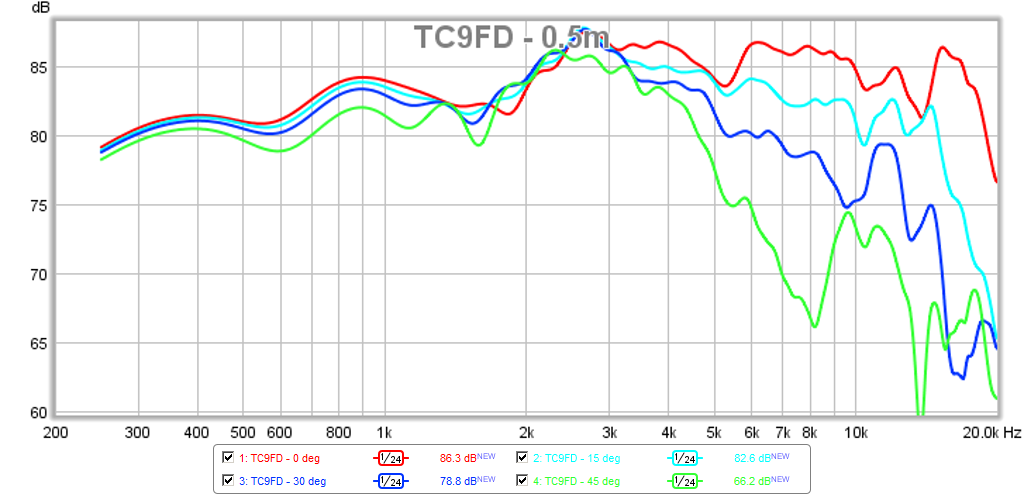
post #20 graphs I looked at, 2.83v 1 meter. Your highest point in graph vs value Vifa's measurement on PE and ~14khz where it kind of ends. Blue line is PE Vifa these 2 points connected and that actually resembles what Vifa graph shows, rising respons, and with red what your 1m 2.83v, similar?, shows.
Attachments
Hobbers,
I admit, my experience in diy speakers and audio is a little over 2 years and I still have much to learn. In my 2 years though, I have built dozens of speakers (look at the index in post 1 - this is just some of the speakers - http://www.diyaudio.com/forums/full-range/223313-foam-core-board-speaker-enclosures.html) and perhaps half as many alignments, some of which are new. I have developed my skills through comprehensive modeling/simulation and building speakers. And as many folks can tell you - I often do sims for others on request. I also measure all my speakers and post measurements and soundclips of my speakers.
My personal experience is relevant but not as important as my body of work posted here in diyAudio. But lets just say that I have lots of degrees, lots of peer reviewed publications, and lots of patents. But I will be the first to admit that I still have a lot to learn from other experts here.
My baffle/speaker choice may seem subjective to you but really was practically constrained. When Barleywater suggested scaling it down - that would work because at least it fits within one sheet of wood. I am always open for improving the measurements and setup.
Let me say that I suspect that if I did not test a MA driver, none of this brewhaha would have happened. Or if I tested one and it measured as advertised, none of this would have happened.
Just a note about the baffle dimensions when testing (cause I've been beaten to death by this one also). There's nothing wrong with not measuring on an IEC baffle. SEAS does this all the time. They measure in a (typically) 20L enclosure and state the baffle dimensions. They then draw a rough line where the IEC baffle measurement would be. It's easy to draw that line in visually if you've done it enough times. If you can't, I recommend EDGE software, although there are other softwares. EDGE will predict the difference between an infinite baffle and the baffle dimensions actually used.
If you use EDGE, I think you'll see that going from an IEC baffle to a sheet of plywood has an indistinguishable difference in response. Especially above 200hz. If you then do a nearfield and merge the results at 200hz, you've got full range data.
I understand what you're saying Bernie, but it doens't deligitimize tests not done on an IEC baffle. The decision to use a baffle other than IEC is subjective. The data gathered is still objective, albeit with qualifiers. I think it's these qualifiers that trip up so many people. On top of that you see people post crappy in room measurements that mean nothing to anyone except the person in that room and the whole measurement game becomes more convoluted.
post #20 graphs I looked at, 2.83v 1 meter. Your highest point in graph vs value Vifa's measurement on PE and ~14khz where it kind of ends. Blue line is PE Vifa these 2 points connected and that actually resembles what Vifa graph shows, rising respons, and with red what your 1m 2.83v, similar?, shows.
This may have to do with what an earlier member said about the more recent TC9FD's having a hotter top end (the latest manufacturer's graph) and my unit from circa 2 years ago. Or it could be variability in particular unit. Let me test another unit and see if there are variations. Like I said though, this is a good variation as you don't want that sharp of a peak.
Just a note about the baffle dimensions when testing (cause I've been beaten to death by this one also). There's nothing wrong with not measuring on an IEC baffle. SEAS does this all the time. They measure in a (typically) 20L enclosure and state the baffle dimensions. They then draw a rough line where the IEC baffle measurement would be. It's easy to draw that line in visually if you've done it enough times. If you can't, I recommend EDGE software, although there are other softwares. EDGE will predict the difference between an infinite baffle and the baffle dimensions actually used.
If you use EDGE, I think you'll see that going from an IEC baffle to a sheet of plywood has an indistinguishable difference in response. Especially above 200hz. If you then do a nearfield and merge the results at 200hz, you've got full range data.
I understand what you're saying Bernie, but it doens't deligitimize tests not done on an IEC baffle. The decision to use a baffle other than IEC is subjective. The data gathered is still objective, albeit with qualifiers. I think it's these qualifiers that trip up so many people. On top of that you see people post crappy in room measurements that mean nothing to anyone except the person in that room and the whole measurement game becomes more convoluted.
Good point Tux, because here is the difference between the small trapezoid baffle (circa 10in wide x 12in tall) and a 20in x 30in baffle:
Let me say that I suspect that if I did not test a MA driver, none of this brewhaha would have happened. Or if I tested one and it measured as advertised, none of this would have happened.
It wouldn't have happened because none of the other manufacturers wish to engage members on an open forum, for obvious reasons.
jeff
I admit, my experience in diy speakers and audio is a little over 2 years and I still have much to learn.
Just advice, take it or leave it. If you want to test drivers and pass judgement like this, I recommend:
1. Read several measurement software manuals (arta, soundeasy, omnimic, REW, etc.)
2. Pick up Testing Loudspeakers. It's a bit dated, but you have some added assurance it's more reliable than some forums posts. I've read it more than once to go back and glean from it.
3. Test, test, test and really hone your skills. I've defended that your measurements are useful, but I'm pretty sure I've never said they're good. Get the reflections out of there and get the resolution up.
4. Try different software programs. I know REW is the free and available one, but so is Holm and Arta and Omnimic's software. Play with them all and you'll expand your knowledge.
Hope that helps. I really enjoy measuring drivers. I've been told my measurements aren't useful, are 4th grade material, need to be redone, don't know what I'm doing, etc. Some of it was true, some of it was ignorance on the accusers part. But I took each one of those comments seriously and did better the next time.
Last edited:
My conclusion, which is subjective, is that this whole thread should be tossed along with all its data and a new thread started once the OP has done all measurements to the industry standard that was once recognized then tossed, and seems to back again, as the best thing to do.
But what do I know, I"m just a woodworker not a measuring kind of guy.
Bernie
nah some data is useful, if you understand the operating test conditions as the OP did inform us. Many (non professional vendors) data is NOT given in IEC setups either, it's more or less given as a guide to sell a feature or two against their own lines or esp. against a competitors optimistic curves.
so the OPs (and others) curves as presented here in this thread is useful in comparison to each other ie the same test setup, and any correlation to vendors data merely provides some extra confidence. yes not very useful as an absolute standard.
BTW this isn't the court room, where when one falsehood is found all the other evidence is trashed.
Last edited:
There have been 3 impedance measures of the CHN70. XRKs, mine & the factory data. Magnitudes of 6, 1, 1 dB respectively. The last 2 taken with the more accurate tools.
As has been explained earlier every FR driver will have 1 or more of these resonances marking where the driver is transitioning from pistonic to resonant behaviour.
dave
Accurate tools often used by professionals, good enough often used by a diy.
Is a diy device DATS v1 computer calibrated to a reference value good enough try compare the two plots, when calibrated i can actually take a reference R L or C and get expected value readings.
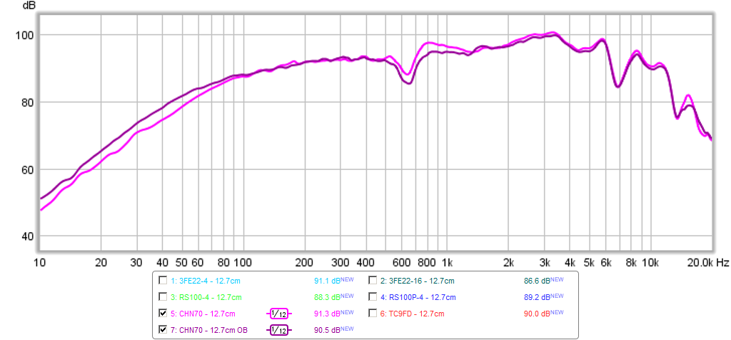
Below both a pro and diy measurements TC9FD, drivers not physical the same my plot show 4 drivers overlayed location is Denmark, planet10 measurement location probably Canada.
Post because can not see why this keep going on when we are at diy site.
Won't do it but could probably buy a CHN70 and planet10 Magnitude figures be amended to 6, 6, 1, 1.
TC9FD planet10 see #343.

TC9FD x 4 see #349.

The Mark Audio drivers are unusual in have 1 primary impedance bump, most FR (that i have measured) show a train of bumps.
I first asked about this on the EL70. Mark supplied the explanation. Backed up by laser interferometry.
dave
Do i misunderstand or what and which is best no bumps or a train, Vifa above have no bumps.
This one my MA A10.2 show a train, two overlays shown one in free air and other low Q sealed box taken thru 4 meter 0.5mm solid core speakercable for both measurements, this probably make 0,4ohm resistance for each core.

At brinesacoustics web site A7.3 A12P shows bumps.
Last edited:

Thank you xrk971 for taking the time to answer my question regarding your experience and know that I'm not questioning experience just the need to state it. In forums it's easy for people to pretend and for a person to say they have experience with out stating what that experience is doesn't help.
Regarding the baffle. I know nothing of measuring and don't have any desire or time to learn it, so my comments were regarding the recognition of a need to follow a industry standard for legitimacy then ignoring that need. Would you except it if another did it?
"Let me say that I suspect that if I did not test a MA driver, none of this brewhaha would have happened. Or if I tested one and it measured as advertised, none of this would have happened."
Or if you contacted Mark and asked about the discrepancies, he could have answered you politely and as two mature adults a proper response could have been found and then presented to the rest of DIY Audio.
I hope you don't mind me adding another or to your statement above? It's meant to give thought not offence.
Hi Ryan, my reason for saying everything should get tossed is something that hasn't been addressed yet and that is the lack of objectivity. As clearly stated by the links I provided there has been very little to no objectivity, its pretty much all been subjective. Unless you disagree with Webster Dictionary?
If measurements have been obtained by a means that are excepted standard and truly objective then the data can stand on its own with out having to be backed up with subjective opinions. If a smaller baffle is an excepted standard then fine by me the measurements don't mean much to me. I'm willing to trust the designers here.
xrk971 I highly commend you for the work you are doing here on DIY Audio.
Keep up the good work and keep on learning, we will all benefit from it.
Bernie
This may have to do with what an earlier member said about the more recent TC9FD's having a hotter top end (the latest manufacturer's graph) and my unit from circa 2 years ago. Or it could be variability in particular unit. Let me test another unit and see if there are variations. Like I said though, this is a good variation as you don't want that sharp of a peak.
Objectively it doesn't matter if your measurements differ in a subjective positive or negative manner from official measurements.
Hi Ryan, my reason for saying everything should get tossed is something that hasn't been addressed yet and that is the lack of objectivity. As clearly stated by the links I provided there has been very little to no objectivity, its pretty much all been subjective. Unless you disagree with Webster Dictionary?
"unless you disagree with Webster" LOL
please reread some answers above your post
- Status
- Not open for further replies.
- Home
- Loudspeakers
- Full Range
- An Objective Comparison of 3in - 4in Class Full Range Drivers