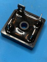
I just took a look at my supply board and it appears you have that connected correctly. However, it is hard to see in the figure but do you have the bridges connected properly? Make sure the AC side is connected to the 2 secondaries and to the bridge's AC side usually indicated with a printed or embossed ~ symbol on both sides. The ones I use have a chopped off corner to indicate the dc+ side and a - symbol on the negative DC side (see attachment). If you connect them correctly, you should see some DC voltage on the DC side of the bridge without any of the rest of the supply connected.
--Tom
Attachments
Thanks. I removed the spare fuse. After all, I know where they are stored.
Also, having removed all outbound connections, when powering up the dim bulb lit up and then dimmed. Both LEDs on the PSU are lit up.
What is my next step? And thanks for all the assistance.
Also, having removed all outbound connections, when powering up the dim bulb lit up and then dimmed. Both LEDs on the PSU are lit up.
What is my next step? And thanks for all the assistance.
Also, the first time i powered this up today and the bulb dimmed, I noticed the right channel LED did not light up. So I replaced it and as I related above, it lit up on the second go. Not sure if I had the first one in reversed polarity or not. Not sure if this contributed to my first failure turning the amp on? Just want to relate everything.
Ok. Will do. I have read to be careful with the trimpot settings when first firing them up. But when I use a screwdriver to turn them, they just go round and round. How do I make sure I don't fry anything out of the gate?
Short pins 2 and 3 on trimpot. put meter on ohms setting and read resistance between pin 1 and the other two which are shorted. dial in zero ohms. repeat for other pot.
Follow Zen Mod's instructions posted up somewhere near the start.
Once you see how the pots are affecting the bias and offset you will soon get it sorted. tiny turns.....
good luck. Brian.
Follow Zen Mod's instructions posted up somewhere near the start.
Once you see how the pots are affecting the bias and offset you will soon get it sorted. tiny turns.....
good luck. Brian.
One way to verify that the trim pots are in min value position before initial power
up is to adjust P1 so that the resistance across R5 is low (close to zero or a few ohms),
and similarly for R6 and P2.
Cheers,
Dennis
up is to adjust P1 so that the resistance across R5 is low (close to zero or a few ohms),
and similarly for R6 and P2.
Cheers,
Dennis
Also, the first time i powered this up today and the bulb dimmed, I noticed the right channel LED did not light up. So I replaced it and as I related above, it lit up on the second go. Not sure if I had the first one in reversed polarity or not. Not sure if this contributed to my first failure turning the amp on? Just want to relate everything.
Check the diode you replaced on the diode mode of your DVM and see if it lights up. Its entirely possible you had some odd over-voltage issue before that blew it, or simply that you had it in backwards. No one has ever done that before! 😉
Yes this was mentioned/clarified on the Whammy thread the other day that you should only has a fuse on the hot side on the incoming AC; not on the neutral (or in addition to the hot side) because most if not all compliance codes now requires this configuration.
The other is a spare you hopefully will not have to use any time soon. 🙂
--Tom
So I removed the second fuse per this discussion and the amp won't work without it. So I can either leave it in or swap out this switch for one that only uses one fuse. Any thoughts on this?
This is the switch currently in the amp: 4304.6090 Schurter | Mouser
No need to remove fuses. Can you test continuity from the power cord to the back of the switch?
It appears that particular switch assembly has fuses in both neutral and live lines if removal of one fuse makes it inoperable.
One work around that makes it safer is to put a much higher current fuse in the neutral side so that if the situation arises, the live fuse will blow.
Here is a good explanation of the single fuse/double fuse situations and why double fusing may be dangerous:
Double Fusing or Fusing Both Sides of the Line - In Compliance Magazine
It appears that particular switch assembly has fuses in both neutral and live lines if removal of one fuse makes it inoperable.
One work around that makes it safer is to put a much higher current fuse in the neutral side so that if the situation arises, the live fuse will blow.
Here is a good explanation of the single fuse/double fuse situations and why double fusing may be dangerous:
Double Fusing or Fusing Both Sides of the Line - In Compliance Magazine
Thanks for the article. I'll have to check my PIMs to see if there is a fuse on neutral or just a spare.
It's too late for me to edit my post #1451.
The safest thing to do if you have a switch assembly with fuses in both neutral and live is to replace it with a single fuse assembly.
The danger of the work around of a higher current fuse in the neutral is that if they are installed incorrectly with the higher current fuse in the live position, the fuse in the neutral line would blow but the live line would still be active.
I checked mine and it does have a fuse on the neutral. I stuck a 5A one in there to go with the 3A on hot.
I will switch my switch
Thanks for the great information. I will pull that switch and replace it.
Thanks for the great information. I will pull that switch and replace it.

V+, V++, and V+++ are all the same electrically. They are connected together. The same goes for V-, V--, V---.
Been an interesting day.
I hooked up the right channel and powered on. The dim bulb stayed on.
I unplugged the right channel and the light dimmed.
I've checked all the wires, things appear to be in the correct place.
What might I consider next to resolve this?
Thanks,
I hooked up the right channel and powered on. The dim bulb stayed on.
I unplugged the right channel and the light dimmed.
I've checked all the wires, things appear to be in the correct place.
What might I consider next to resolve this?
Thanks,
I haven't built a F5 so I can't help you with the amplifier board trouble shooting. However to get the process started, if you post clear, well lit, and high def pictures of the amp overall to show wiring and also individual pictures of the amplifier boards, I'm sure others will help you to get it running.
Also, is your light bulb 100W?
Also, is your light bulb 100W?
- Home
- Amplifiers
- Pass Labs
- An illustrated guide to building an F5