Yes, but don't use the same bolt that the safety ground uses. The safety ground should always
have its own mechanical/electrical ground connection.
have its own mechanical/electrical ground connection.
Last edited:
The safety ground is crucial to the (naturally) safety of the amplifier.
If it becomes disconnected, there is no path for the fault current,
should there be a dangerous electrical short to the chassis.
Then the fuse and/or breaker then would not open. The mechanical connection
is more secure and reliable if the safety ground wire is bolted down alone.
The terminal crimps on both ends of the safety wire from the IEC socket are equally important.
Breakers and Ground Wires
Last edited:
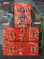
Here is the chart embedded as a graphic
Looks good chiptech.
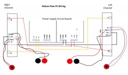
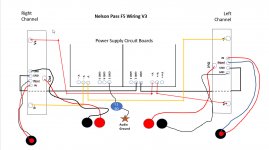
One more thing: you need to connect the Audio ground to protective earth through a CL60. As is shown on PSU diagram on F5 paper.
I think you have to put the core on the input wire to the IN and the shield to the GND.
I'm up to this stage as well and that's what I was told and is what I can see from the other amp builds.
Someone, please correct me if I am wrong.
I'm up to this stage as well and that's what I was told and is what I can see from the other amp builds.
Someone, please correct me if I am wrong.
"I think you have to put the core on the input wire to the IN and the shield to the GND."
Can you say a little more. I can't parse out your connections.
Thanks
Can you say a little more. I can't parse out your connections.
Thanks
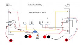
Thanks for review. I've updated the chart.
The “GND” in the power supply board is actually your Audio Ground.
The star you put in this picture should be the protective earth.
Correct connection to protective earth is very very important, I suggest you check through 6l6’s pictures for details on:
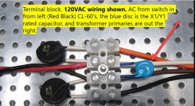
- IEC inlet wiring
- CL60 thermistors to be placed in series with your transformer primary windings
For the sake of completeness.
Not really complicated but important to get it right.
"I think you have to put the core on the input wire to the IN and the shield to the GND."
Can you say a little more. I can't parse out your connections.
Thanks
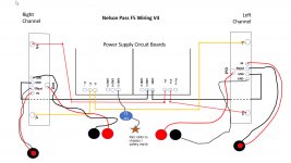
Chuckd’s point is: typically in the rca connectors: signal is in the center and ground in the outside. However in your picture the orientation is swapped. (Red in outside, black inside)
If you are aware of the orientation of the rca jacks, than it is all good
"I think you have to put the core on the input wire to the IN and the shield to the GND."
Can you say a little more. I can't parse out your connections.
Thanks
Like Syracuze said...you have the core on the RCA going to GND and the shield to IN. You need to swap that around.
Since you actually drew the RCA cable with a core and shield, you're familiar with its construction but you just have the parts going to the wrong connection on the gain stage board.
See my rudimentary picture.
Hope it helps.
Attachments
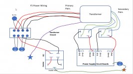
1) Left channel is showing both wires to the same point on what I think you're drawing to represent your RCA input jack, but I think you've got the idea.
2) The CL-60 connects PSU GND to chassis / safety earth, not to audio GND.
2) The CL-60 connects PSU GND to chassis / safety earth, not to audio GND.
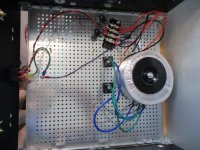
Going on a year ago, with a LOT of help from the folks in the Pass forums I built my first two kits. First a Korg preamp. Then an F5. I've thoroughly enjoyed them including climbing the learning curve to build them. The combination sounds fantastic. I swap them in to power my Tekton Ulfbert speakers with either a digital input or with my turntable. I recently purchased a CNC Router and I am constructing a pair of DIY Lore speakers with the help and blessing of Eric at Tekton. So I'm currently working toward an all DIY analog system. Likely to build a Pearl phono preamp next. Just wanted to say THANKS to the community and encourage anyone else considering an F5 to forge ahead. It is an awesome value and a great learning experience.
- Home
- Amplifiers
- Pass Labs
- An illustrated guide to building an F5