Capacitor Voltage Rating depends on your Transformer's Secondary Voltage rating!!!
I would appreciate any guidance on this comment from the BOM Capacitor "Voltage Rating depends on your Transformer's Secondary Voltage rating!!!"
I have a Antek AS-4224 400VA transformer. I plan to use it with either 15,000 35V or 22000 35V.
Can I use either? Or point me toward where to research 2nd windings.
Thanks
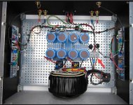
You have two 24VAC secondaries. That's about 32VDC each after rectification.
You should use at least 35V rated capacitors, but 50V capacitors would be better and last longer.
You should use at least 35V rated capacitors, but 50V capacitors would be better and last longer.
Last edited:
You want to ensure that the voltage rating on the caps has a bit of margin. Cap rating is for maximum DC.
In short, if you're using a transformer with 24V secondaries - 24VAC x 1.4 ~ 33.6VDC ... 50V caps have been more widely used.
re: research - the data sheet on the transformer will tell you the secondary voltage.
I haven't been following the thread too closely, but is there a reason you're using 24V secondaries in an F5? I searched for posts by you. 18V is the most common for a standard F5. I've seen 20, and maybe 22 used occasionally, but personally I've never seen 24 except I think on an F5 Turbo. That could be my lack of knowledge and not reading the full thread. Someone else will surely chime in as to whether that transformer is suitable for this build taking into account the JFETs etc. That's out of my realm.
Edited to add... Rayma beat me to it... I had to pause mid post.
Thanks to both of the responses. I also have a Antek AS-4218 400VA 18V transformer.
Sounds like that is the better option?
Sounds like that is the better option?
So with the 18V transformer I have either 15,000 uf 35V or 22000uf 35WVDC
I thought I'd go with the higher caps?
I thought I'd go with the higher caps?
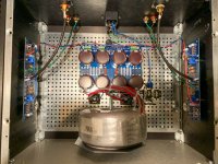
Yes, my Primare A20 has 4 x 10,000 uF, that will be upgraded to 4 x 15,000 Mundorf Mlytic AG 🙂
And that is considered a High-End Amp, but I like my F5 better.
And that is considered a High-End Amp, but I like my F5 better.
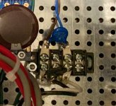
Looking for this terminal block
I have searched for the white plastic terminal block shown in the assembly guide without any success. I've found one, but it is pretty large. I'd appreciate it anyone can point me in the right direction.
Thanks,
Chip
hopefully the photo will show up
I have searched for the white plastic terminal block shown in the assembly guide without any success. I've found one, but it is pretty large. I'd appreciate it anyone can point me in the right direction.
Thanks,
Chip
hopefully the photo will show up
Attachments
I have searched for the white plastic terminal block shown in the assembly guide without any success. I've found one, but it is pretty large. I'd appreciate it anyone can point me in the right direction.
Thanks,
Chip
hopefully the photo will show up
For future reference, this is a compatible part:
HE1WPR/06 Altech | Mouser
Although, per previous post, there are better options.
I used this terminal barrier:
TB100-04 Bussmann / Eaton | Mouser
I first soldered the NTC lead to a solder tab with internal lock washer, and screwed that to the terminal barrier.
Attachments
I am using the TB100-04 Bussmann / Eaton | Mouser and the holes don't align so I will have to drill one hole to make it work.
Thanks
Thanks
You can find similar terminal block at Home Depot. Electrical department, rare to find diy supplies locally.
- Home
- Amplifiers
- Pass Labs
- An illustrated guide to building an F5