You basically built a w-bin BP6P without folded wings.
Square up the middle chamber below.
Make the center port the same CSA as the middle chamber.
Now you have BW's folded T tube BP6P.

Square up the middle chamber below.
Make the center port the same CSA as the middle chamber.
Now you have BW's folded T tube BP6P.
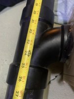
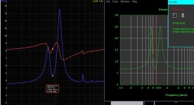
Driver is mounted dead center of a 46” (3”diameter/45cm2) pipe. Modeled as a 90cm2 58.42cm (23”) 1/4 wave pipe.
i didn’t add the short distance of the ‘T’
i didn’t add the short distance of the ‘T’
Attachments

Last edited:
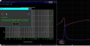
quick and dirty mic at one of the open ends and horn resposne(red)
acts exactly as it’s 1/4 cousin would?
A plain pipe isn’t a Bassxreflex enclosure. it is just a didgeridoo with resonances based EXCTLY on its 1/4 length /1,/3,/5,/7,/9…?That pic is exactly what I'm talking about when I said we are trying to model a BR type enclosure. Remember, TL's are fancy or exotic BR enclosures.
You switched it up by trying to use Ap/Lpt with an offset driver.
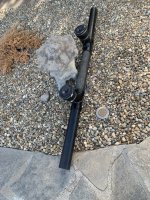
Your Pic shows there is no tube or chamber on the other side of the driver.
im using scraps and junk for an experimentAl skunk works resonator for area51 and you’re busting my nuts about a little frame around the driver so it can be siliconed into a pipe T? 👽
Last edited:
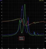
That pipe and then i (accidentally for science) flipped the polarity on one of the drivers and Fb nearly halved? Wish I could imagine what was going on inside for that to combine as such. Suck and blow at the locations for the second resonace ?
Attachments
Last edited:
You basically built a w-bin BP6P without folded wings.
Square up the middle chamber below.
Make the center port the same CSA as the middle chamber.
Now you have BW's folded T tube BP6P.
View attachment 1357617
something like this ??
A very simplitic way to describe it.
For explaining why having a TML working at 200 Hz sounds bad, absolutely sufficient. He knows what a TML is but didn't know why that is bad.
Given a fixed length, the phase of the terminus oiutput changes in relationship to the direct radiation. In an undamped line this creates ripples in the frequency response. One of the challenges of a TL that aim to use the terminus output to enhance bass extension, the fundemental needs to match phase and we want to suppress all those about by creating an acxoustic low pass filter on the terminus output. Where the fundament and harmomic placement is dependant on pipe length and taper.
That's correct ofc but not necessary to explain it there.
Traditionally this has been the role of fibrous damping, but since King’s model illustrated how other low pass filters can be used. Most notably things like driver offset, Mass-Loading, expanding line sections at bends (ie deflectors are often counter-productive).
With a T-line tapering is counter-productive and you know that. Especially since the question was about a literal tube.
Ok, thanks.Depends exactly what you're doing. If you're creating something with an internally mounted drive unit, then in essence it's an extreme version of a BP6 or H-frame since the front & rear of the driver excites physically isolated 1/4 wave pipes, & if those are of different lengths, then it's akin to a DSL style [double] tapped horn. If it's a pipe open at both ends that's simply excited at a given location by either the front or rear of the drive unit, it's a 1/2 wave pipe.

You're talking about a single-tapped 1/2 wave pipe here (as in a pipe open at both ends & excited only by the front or rear of the driver, rather than with an internally mounted unit like a Wave Cannon, which is a 1/4 wave variation on a BP6)?
Not that it matters really, because the answer is the same: that isn't actually true. Or rather, it has an effect on the overall load characteristic (since assuming a single-tap the pipe is a summed system -you don't treat 'one end' separately to the other as such). That doesn't mean taper is counter productive though, any more than it's counter-productive for a 1/4 wave design. It might be; if the target goals indicate it may be beneficial, e.g. in lowering the fundamental for a given physical length, Vp & altering the location & amplitude of the harmonic modes, then it is isn't.
Not that it matters really, because the answer is the same: that isn't actually true. Or rather, it has an effect on the overall load characteristic (since assuming a single-tap the pipe is a summed system -you don't treat 'one end' separately to the other as such). That doesn't mean taper is counter productive though, any more than it's counter-productive for a 1/4 wave design. It might be; if the target goals indicate it may be beneficial, e.g. in lowering the fundamental for a given physical length, Vp & altering the location & amplitude of the harmonic modes, then it is isn't.
Driver is mounted dead center of a 46” (3”diameter/45cm2) pipe. Modeled as a 90cm2 58.42cm (23”) 1/4 wave pipe.
i didn’t add the short distance of the ‘T’
It's still an offset driver BP6P design.
View attachment 1357635
quick and dirty mic at one of the open ends and horn resposne(red)
acts exactly as it’s 1/4 cousin would?
Aren't QW's bandpass enclosures?
Positive flare quarter wave port or tube = TH or BP6S.
Straight flare quarter wave port or tube = TQWP, TQWT, or BP6S.
Negative flare quarter wave port or tube = T-TQWP, T-TQWT, or BP6S.
Positive flare quarter wave BP4 = FLH.
That pipe and then i (accidentally for science) flipped the polarity on one of the drivers and Fb nearly halved? Wish I could imagine what was going on inside for that to combine as such. Suck and blow at the locations for the second resonace ?
Those measurements are ALL bandpass responses.
something like this ??
Make the center port the same CSA as the middle chamber (basically open back) and you have BW's folded T type BP6P enclosure.
With a T-line tapering is counter-productive and you know that. Especially since the question was about a literal tube.
Positive tapering = efficiency, low, and big enclosure.
Negative tapering = inefficiency, low, and small enclosure.
Hofmann's Iron Law is still winning.
THAT is dual driver TL. You have no wooden chamber in front of the driver's.The only ‘fancy‘ version I see as useful? (I got advice from Martin King on Facebook) Driver offset at the second resonance Vmax at both locations in the pipe ?
TL's are fancy BR's. Remember, once a BR's port is at least 72in or 6ft, then BR becomes a TL.
In HR, you can model a BP6P with the Nd, OD, CH, and BP6P functions.
In HR, you can model a TL with the Nd and OD functions.
With the Nd function, you can model TL's without using the segments, just like a BR enclosure. That fact right there tells you they are the same enclosure type. All you need is Vrc/Lrc and Ap/Lpt. Shoot, you can use Vtc/Atc and Ap1/Lp and get the same results.
- Home
- Loudspeakers
- Subwoofers
- An idea: A T-line with both ends open