The transmission line works because of the phase shift. At 200Hz the phase turn sounds bad. Such a open tube will most likely be a subwoofer and if it plays that high, you can locate it. So it's not really helpful.
Depends exactly what you're doing. If you're creating something with an internally mounted drive unit, then in essence it's an extreme version of a BP6 or H-frame since the front & rear of the driver excites physically isolated 1/4 wave pipes, & if those are of different lengths, then it's akin to a DSL style [double] tapped horn. If it's a pipe open at both ends that's simply excited at a given location by either the front or rear of the drive unit, it's a 1/2 wave pipe. The Bose Wave Cannon falls in the former category.Hi, I have a new question: if both are open ends, then would it be possible to align two resonances, like: 50 Hz, 200 Hz, to extend the frequency range of the transmission line box?
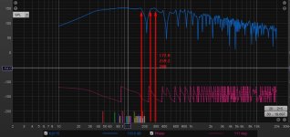
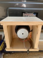
I built one for fun (folded up so they exit together) and it sounds nasty when left alone to resonate and ring. I need to adjust the rew scaling to really show this better
Attachments
Last edited:
The closed pipe section or throat cannot be opened with the OD functions.The closed pipe section actually has an exit/vent that is available in the ‘Ap/Lpt’ description in this unique part of the ‘OD’ and ‘Od1’ sections.
Ap/Lpt = behind the driver.
Ap1/Lp = in front of the driver.
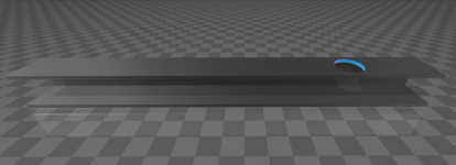
We need to open the left side of the offset driver.
Last edited:
Below is a BP6P enclosure.This must have a pretty legit dsp/parametric EQ cleaning up the high frequency resonances and a steep crossover?
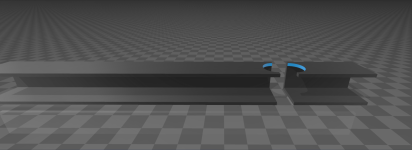
We want the driver mounted offset from the dual open ended pipe.
Do you mean without a low pass filter?it sounds nasty when left alone to resonate and ring.
Yea sir, there’s nothing in horn response that allows us to describe an open/open ended pipe (or how intersting it would be to move the driver around to velocity max for particular resonances in one) . but can we just assume the same locations in the closed/open end pipe will be in the half wave pipe at similar distances from ‘center’? And moving the driver around doesn’t create ‘another pipe‘ affectively and more resonances ?Below is a BP6P enclosure.
We want the driver mounted offset from the dual open ended pipe.
View attachment 1357563
No, it needs much more than just a simple filter . It’s a train wreck that only dsp can tame and the fundamental is far too overdamped to be an exciting ‘subwoofer’. I sent a really annoying sound clip off my phone to @maxolini of it playing without a crossover to torture him 😝
if ‘paraflex’ sounds as good as they claim, then the work done to clean that up (with offsets and vent position) must be respected /recognized imho. It’s like taming a raging bull with Tourette’s
if ‘paraflex’ sounds as good as they claim, then the work done to clean that up (with offsets and vent position) must be respected /recognized imho. It’s like taming a raging bull with Tourette’s
Last edited:
No, because we are trying to model a BR type enclosure. As soon as you put a chamber in front and behind the driver, it's a bandpass enclosure.can we just assume the same locations in the closed/open end pipe will be in the half wave pipe at similar distances from ‘center’? And moving the driver around doesn’t create ‘another pipe‘ affectively and more resonances ?
i guess you’re not talking about the same thing. I’m referring the original question by maxine01. The parallel pies are entirely different
The transmission line works because of the phase shift
A very simplitic way to describe it.
Given a fixed length, the phase of the terminus oiutput changes in relationship to the direct radiation. In an undamped line this creates ripples in the frequency response. One of the challenges of a TL that aim to use the terminus output to enhance bass extension, the fundemental needs to match phase and we want to suppress all those about by creating an acxoustic low pass filter on the terminus output. Where the fundament and harmomic placement is dependant on pipe length and taper.
Traditionally this has been the role of fibrous damping, but since King’s model illustrated how other low pass filters can be used. Most notably things like driver offset, Mass-Loading, expanding line sections at bends (ie deflectors are often counter-productive).
dave
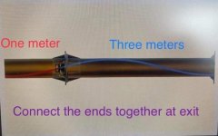
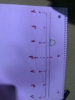
For a better understanding of the transmission line in my question.
These are images of a straight tube measuring 215 cm and divided.
If we divide according to the location of the speaker hole, this would be: 172 and 43 cm, which corresponds to: 50 and 200 Hz.
[Other] If my calculation is correct, the modes of the three-dimensional space are related to 1/2 of the wavelength in the width and height of the transmission line, so if the width and height are at most 21 cm, the transmission line can go up to 800 Hz.
Attachments

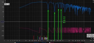
50 and 200 cm will be the resonating length of 344 and 86 hz in the pipe with both ends open. But the driver position it’s in has me baffled(no pun intended 😃). Intersting thing to figure out!

That pic is exactly what I'm talking about when I said we are trying to model a BR type enclosure. Remember, TL's are fancy or exotic BR enclosures.I had to draw it so I didn’t sound confusing (sorry). Will this remove that resonance ?
You switched it up by trying to use Ap/Lpt with an offset driver.
Your Pic shows there is no tube or chamber on the other side of the driver.
This is a BP6P enclosure that can be modeled with the compound horn (CH) function in HR.
The wood chamber has to go to still be an ODTL.
THIS:

is NOT this:

The wood chamber has to go to still be an ODTL.
THIS:
is NOT this:
- Home
- Loudspeakers
- Subwoofers
- An idea: A T-line with both ends open