No special requirements for the reservoir capacitor, except that we want reasonably low ripple, let’s say no more than 1Vpp. At 100 Hz mains, 18 mF capacitor would have 1Vpp ripple at 1.8 A load. So, it seems fine for F3 single channel build.
Actually, I was counting on using 2 of these capacitors in parallel, which adds up to a total of 36mF per channel in position C1.
Assuming the following conditions:
Mains frequency = 50Hz
Load = 1.8A (taken from your example)
C1 capacitance = 36mF
Under these conditions C1 would have a ripple of just 0.5Vpp, making this a better configuration for C1.
Doing the math:
Vpp(ripple) = I / (2 f C)
Vpp = 1.8A / (2 x 50Hz x 0.036F) = 0.5V
Thanks.
Because he has enough capacitors?
BTW, compared to 18 mF, 36 mF will allow regulator to operate at 0.25V lower voltage drop.
Ripple at output doesn’t exist in both cases (several uV only).
BTW, compared to 18 mF, 36 mF will allow regulator to operate at 0.25V lower voltage drop.
Ripple at output doesn’t exist in both cases (several uV only).
There will be integrated single rail supply with active rectifier in the future. No over voltage but soft ramp-up. PSRR should be good up to 100 MHz range. It’ll require some time to finish design, build prototype and perform testing. Current state, several days in project:


That's right! The initial idea was to build a regular CRC PSU for which I bought these capacitors. But now that I've decided to build a PSU around the R21, I'll simply repurpose the capacitors.Because he has enough capacitors?
I'll implement C1-R21-C2 with significantly less capacitance at C2, as per Tombo's recommendations (see bellow).
Output capacitor (C2) can be small as regulators don’t require anything special for stability, but larger capacitors provide better transient response on high dynamic load. So, 470 uF is minimum and several mF (2200 – 4700 uF) is enough.
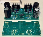
Made a basic dual mono board with nested R21-P modules. Everything tested good. These are for a transformer-coupled SIT amp I’ve been planning and I’m waiting on the OPTs to be built, so it’ll be another month or two before I can try it out in its intended use case.
From what Tombo has said, dual mono is probably unnecessary with these regs… but I couldn’t resist 🙂
From what Tombo has said, dual mono is probably unnecessary with these regs… but I couldn’t resist 🙂
Attachments
Here are the files, though probably best to see what Tombo comes up with for his integrated options.
Attachments


Great solution with the carrier board. No objections to wiring, performance will be good.  😁
😁
IME, dual mono has some small advantage in soundstage because channel grounds are completely separated.
New integrated supply will have great PSRR up to MHz range thanks to use of additional Murata RF filter. Measuring prototype, PSRR is slightly better below 20 kHz, and doesn’t drop below 75-80 dB all way up to 400 kHz. Can’t measure past 400 kHz, but PSRR will not drop below 60-70 dB far into MHz range. With all those SMPS around, it could be useful.
😁IME, dual mono has some small advantage in soundstage because channel grounds are completely separated.
New integrated supply will have great PSRR up to MHz range thanks to use of additional Murata RF filter. Measuring prototype, PSRR is slightly better below 20 kHz, and doesn’t drop below 75-80 dB all way up to 400 kHz. Can’t measure past 400 kHz, but PSRR will not drop below 60-70 dB far into MHz range. With all those SMPS around, it could be useful.
What a fun project. Thank you Tombo56 for your build guide, total lifesaver for me. I couldnt figure out why my postive regulator wouldnt work, I tried replacing all the zener diodes in case I messed one of them up, IE the 3.3 and the 33. But it still didn't work. It would just go to full voltage, which in my case was 44 volts and then slowly drop down to 6.8 volts and the trim pot had no effect. Then I remembered something in the build guide about the silk screen markings denoting the front of the transistor. Yup I reversed the 1381 and the 3503, flipped them around and the regulator now works flawlessly. Still waiting for my 1381's to show up from mouser and newark.
This is my gaggle of regulators, one pair for my class ab/d amp experiments(ax-14, tda7293, Mooleys Mosfet) and the other 2 pairs will be for my dual mono setup in a XA252.
This is my gaggle of regulators, one pair for my class ab/d amp experiments(ax-14, tda7293, Mooleys Mosfet) and the other 2 pairs will be for my dual mono setup in a XA252.
Attachments
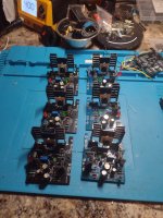
That’s a lotta regulators waiting for some action. Are those heat sinks for testing only purpose?
They could suffice for class AB & D, but not for class A with idle current in the > 1 A range.
Another point is that for class AB & D, regulators should operate with about 4-5 V voltage drop as there will be higher voltage variation on the reservoir capacitor due large current change between idle and full power amplifier operation.
Any regulators verification should be performed with some capacitance at input and output.
Hi Tombo. Is there an ideal place/method to measure the current passing through the R21-P? Apologies if I’ve missed this written up elsewhere. I also don’t want to make assumptions on my own 🙂

- Home
- Amplifiers
- Power Supplies
- An arguably better replacement for the resistor in a CRC power supply - R21 PS module